®
5
WARNING
: ALL ACTIONS RELATED TO THE INSTALLATION, SERVICE AND
OPERATION OF GAS PILOT MAY ONLY BE CARRIED OUT BY A TRAINED AND
QUALIFIED PERSONNEL.
WARNING: STRICTLY OBSERVE THE TEMPERATURE LIMITS FOR PILOT
AND IGNITER ROD MOUNTED INSIDE. IN THE CASE OF EXPECTED WORK AT
THE LIMIT OF PERMISSIBLE OPERATING TEMPERATURES, APPROPRIATE
MEASURES SHOULD BE TAKEN (E.G. CHANGE OF THE MOUNTING POSITION).
WHEN BOILER OR HEATER INSTALLATION IS IN OPERATION ALWAYS KEEP
THE AIR ADJUSTMENT SLEEVE OPEN TO ENSURE THE PROPER AIRFLOW.
7. INSTALLATION
During the installation, all components must be protected from impact or bending.
WARNING: DURING PILOT INSTALLATION THE RECOMMENDATIONS IN THE
APPENDIX 2 SHOULD BE STRICTLY OBSERVED.
Pilot
SP-32-
NG/PG-
ND
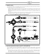
is designed such that its air tube can be welded directly to the burner plate, or placed in the
mounting tube (see Fig. 2).
It should be noted that the insertion depth should be fitted in a manner that will allow full air adjustment by
adjustment sleeve (insertion depth cannot exceed the
“L” value
– see Fig. 1).
Pilot air tube is made of stainless steel, mounting tube is made of carbon steel which must be noted for welding.
Note: Particulates entrained in the gas could block the pilot’s gas orifices so gas supply line should be equipped
with an effective strainer unit.
REMARK
: IN CASE OF ANY DOUBTS REGARDING INSTALLATION OF THE
PILOT CONSULT WITH THE MANUFACTURER.
7.1 MOUNTING TUBE
The mounting tube, if used, should be attached to the burner plate using bolts or welding (see Fig. 2). If it is not
possible to use one of mounting tubes proposed above, a different type can be used, bearing in mind that its inner
diameter should be properly matched to the outer diameter of the pilot air tube to be able to fit and fix the pilot in
a tube with proper clearance.
In case of an application including a mounting tube proceed in the following way:
a)
Based on assembly drawings mark and cut a hole in the burner plate with a diameter slightly larger than
the diameter of the mounting tube.
b)
The mounting tube for welding: slide the mounting tube for welding in the hole and set it in the correct
position (insertion depth and proper angle
relative to the main burner nozzle position).
c)
The mounting tube for welding: weld using the electrode appropriate for the material.
d)
If the flanged mounting tube is used, bolt it to the burner plate after drilling the correct sized holes.
e)
For both types of mounting tube the clamp assembly with
screws and gasket
provides a fast and reliable
mounting and dismounting of the pilot.
7.2 GAS ASSEMBLY AND AIR TUBE
a)
The position of the electrical igniter rod tip in relation with the orifice-stabilizer assembly of pilot should
be checked following information in p. 4. The correct position for different types of electrical igniter rods
should be taken into consideration (see Fig. 1).
It should be remembered that the rod tip positioning against the stabilizer plate in the pilot gas part
assembly (pos. 1 on Fig.1) should be done outside the air tube only.

