background image

4

Optional Mounting Configurations for Hazardous Areas

FIGURE 2.

45UV5 SCANNER IN NEC/NEMA HAZARDOUS AREA HOUSING

FIGURE 3.

45UV5 SCANNER IN ATEX HAZARDOUS AREA HOUSING

INSTALLATION

1.

The best scanner sighting results are obtained when the scanner is aimed so that the scanner
(viewing) center line intersects the burner center line at a slight angle, as shown in Figure 4. The
area of maximum ultraviolet radiation is near the base of the flame envelope. If only one scanner
is used per burner, the intersection should be made so the line of sight or viewing angle can also
see the igniter flame. Consideration must be given to burner air rotation (burners have clockwise
or counterclockwise air rotation). Figure 5 illustrates how scanner location is influenced by the
igniter position and air circulation. Physical obstructions such as air register blades should not
fall within the scanner’s line of sight.

17 1/4

8.25 (210)

FIREYE FLAME SCANNER

16 3/16

(412.79)

 ± 3/64 (1.2)

(439.88)

7 3/4

(196.85)

1" NPT

NIPPLE

1 1/4" PLUG

1 1/4" NPT CONDUIT
ENTRY

P/N 45UV5-1000EX (Includes Model 

45UV5-1000 Scanner)

P/N 45UV5-1101EX (Includes Model 

45UV5-1101 Scanner)

Housing Rating:
Class I, Div. 1& 2 Groups C,D
Class II, Div. 1, Groups E, F, G
Class III
NEMA 3, 4, 7 CD, 9 EFG
Weight: Approx. 18 lb. (8.2 kg.)

(NOT FURNISHED)

P/N 45UV5-1000CEX (Includes Model 

45UV5-1000 Scanner and p/n 35-128 

NPT Mounting Flange).

P/N 45UV5-1101CEX (Includes Model 

45UV5-1101 Scanner and p/n 35-130 

BSP Mounting Flange).

Housing Rating:
Exd II C T 6
IP 66
Weight: Approx. 7.6 lb. (3.5 kg.)

DIMENSIONS IN INCHES (MM)

4.02

(102)

4.41

(112)

MOUNTING FLANGE

8.10 (206)

3/4" NPT THREADED

OPENING FOR 

COMPRESSION-STYLE

CABLE GLAND

(NOT FURNISHED)

3/8" NPT

THREADED 

OPENING FOR

COOLING AIR

1" THREADED

OPENING

3.56
(90)

(INCLUDED)      

Содержание 45UV5 Series

Страница 1: ... For burners firing steam atomized oil or pulverized coal Fireye recommends the use of infrared IR scanners Fireye offers a complete line of infrared scanners best suited for these applications APPLICATION When used with a Fireye amplifier the 45UV5 scanner provides flame failure protection on single and multi burner industrial applications such as electric utility boilers power boilers and large ...

Страница 2: ...e oil resistant gaskets The quartz lens is a planoconvex type which increases the scanner s sensitivity up to 400 percent A hinged mount is pro vided to permit easy access for cleaning the lens A double screw and keyhole slot arrangement per mits quick removal of the housing from its mount The scanner has a 1 fitting for mounting to a threaded sight pipe and a 3 8 threaded connection for purge air...

Страница 3: ...pping Temperature Range Maximumoperating 200 F 93 C Minimum operating 40 F 40 C Optical Range 190 to 250 nanometers No response to infrared radiation or visible light Purge Air Source Clean ambient Volume Required 4 SCFM 113 L min 4 water column above furnace pressure minimum at 3 8 inch threaded housing inlet or 4 SCFM at 1 inch wye fitting in scanner sight pipe Temperatures near the upper limit ...

Страница 4: ...gniter position and air circulation Physical obstructions such as air register blades should not fall within the scanner s line of sight 17 1 4 8 25 210 FIREYE FLAME SCANNER 16 3 16 412 79 3 64 1 2 439 88 7 3 4 196 85 1 NPT NIPPLE 1 1 4 PLUG 1 1 4 NPT CONDUIT ENTRY P N 45UV5 1000EX Includes Model 45UV5 1000 Scanner P N 45UV5 1101EX Includes Model 45UV5 1101 Scanner Housing Rating Class I Div 1 2 G...

Страница 5: ...t the inter fering vane s should be trimmed to assure an unobstructed viewing path at all firing levels 5 Mount scanner sight pipe by either Centering a swivel mount P N 60 1664 3 NPT or 60 1664 4 BSP over the hole and installing the sight pipe on the swivel mount or Inserting the end of the sight pipe into the hole aligning the pipe to the desired viewing angle and tack welding Welding must be ad...

Страница 6: ...ls of flash or soot or for hot environments to maintain scanner internal temperature within specification 8 The scanner sight pipe should be as large as is practical Ideally the sight pipe should increase one inch in diameter ID for every foot in length Under most circumstances a sight pipe diameter increase of one inch should be adequate for an increase in length of three feet 1m When apply ing t...

Страница 7: ...Signal readings referred to in this procedure are as displayed on a 0 3 VDC Fireye flame signal meter P N 38 54 38 55 38 56 1 2 1 If using analog bargraph meter P N 38 88 the flame will be properly sighted when there are 5 8 LEDs illuminated 2 When used with the 25SU3 2000 series amplifiers and appropriate power supply the required flame signal strength in terms of pulses per second will be determ...

Страница 8: ...Scanner 1 Apply power to scanner and control 2 Start igniter 3 Adjust scanner sighting so that ignition spark and igniter flame are not detected Test should be conducted with maximum igniter flame and with both minimum and maximum air flow Note This step may not be practical with Class 1 igniters but may be desirable with Class 3 4 Start main burner 5 Adjust scanner sighting to detect main burner ...

Страница 9: ... Refer to the control bulletin for further information The detector is shipped in the MAX signal position If the tube position is changed in the field and the scanner is later replaced verify that the signal strength is not excessive METHOD 2 45UV5 SCANNERS WITH ENGINEERING CODE 04 AND HIGHER built after mid 2008 The sensitivity is adjusted by changing the position of the orifice plate in front of...

Страница 10: ...nt with an orifice retainer or the orifice can be placed within a 1 inch union not provided C D E F G A B C D E F G A Tube see note B Shutter Bracket 61 2914 1 C Shutter Bracket lens see note D Gasket 29 248 E Lens Holder 82 95 F Lens Retainer 16 103 G Lens Assembly see note Note Refer to MAINTENANCE section for detailed list of part numbers A I Orifices 0 062 0 5 DIA J Orifice Retainer 34 181 K H...

Страница 11: ...eter 0 078 13C 1 53 121 4 Orifice Diameter 0 093 13D 1 53 121 5 Orifice Diameter 0 109 13E 1 53 121 6 Orifice Diameter 0 125 13F 1 53 121 7 Orifice Diameter 0 187 13G 1 53 121 8 Orifice Diameter 0 250 13H 1 53 121 9 Orifice Diameter 0 375 13I 1 53 121 10 Orifice Diameter 0 500 13J 2 34 181 Orifice Retainer FIGURE 15 ORIFICE LOCATION FIGURE 16 SCANNER WITH ORIFICE Note There is an inverse relations...

Страница 12: ...er Refer to the Control and Scanner Wiring sec tion for further information Fireye scanner cable Part No 59 470 4 conductors 18 AWG 2 conduc tors 22 AWG common shield or Part No 59 471 4 conductors 18 AWG 4 conductors 22 AWG common shield is used for wiring connections between the scanner s and the control terminals Each wire is color coded for connection as follows BLACK L or AC hot terminal RED ...

Страница 13: ...ontrol bulletin Group I Fireye Controls A blocking diode Fireye Part Number 101 78 must be used when a solid state type scanner is used in parallel with a UV scanner Connect the diode in series with the lead from terminal 14 in the UV scanner as shown in Figures 16 and 20 This is to avoid damaging the solid state scanner If the appli cation requires that only one scanner be in use at any time the ...

Страница 14: ...be used when a solid state scanner is used in par allel with a UV scanner Connect the diode in series with the lead from terminal 14 in the UV scanner as shown in figures 20 and 21 Group VI Amplifiers 2000 Series A blocking diode is not required when a solid state scanner is used with a UV unit See Figure 22 FIGURE 17 GROUP I CONNECTIONS NOTES 1 DIODE PART NUMBER 101 78 CONNECT AS SHOWN IN SIGNAL ...

Страница 15: ...8 CONNECT AS SHOWN IN SIGNAL LEAD 14 OF UV SCANNER WHEN USING WITH SOLID STATE SCANNER 2 CAPACITOR PART NUMBER 7 1143 CON NECT AS SHOWN TO POWER SECOND SCAN NER FROM ONE AMPLIFIER 3 RESISTOR 1 MEG OHM 1 4 WATT LA 1A 14 C P 1 C WHITE BLACK GREEN 14 L 1 C 14 WHITE BLACK GREEN SHIELD SHIELD SHIELD SHIELD SCANNER A 45RM1 2 SCANNER B 45UV5 DIODE SEE NOTE 2 3 1 Group III Non self checking units capable ...

Страница 16: ...ANNER TERMINAL NO 14 1 P C 14 45RM1 2 C 14 1 L 45UV5 26 LB 1 LA C 14 RED BLACK WHITE GREEN RED BLACK WHITE 101 78 GREEN 45RM4 or 45UV5 1 L C 14 2 1 3 1 45FS1 or 45UVFS1 RED BLACK WHITE GREEN RED BLACK WHITE GREEN 101 78 120 VAC 24 VDC Group V Self checking units capable of operation with one or two scanners If two models 45UV5 scan ners are used the diode is not required Connect scanner cable shie...

Страница 17: ...AL COMMON SHUTTER POWER SHIELD Z2 Z4 D4 D2 POWER SUPPLY 19UVPS 2120 19UVPS 2220 3 2 1 SCANNER B 14 C 1 P SIGNAL COMMON SHUTTER POWER SHIELD 7 7 14 C 1 P QUICK DISCONNECT PINS IF USED INTERNAL TERMINALS INTERNAL TERMINALS QUICK DISCONNECT PINS IF USED Z6 D6 GREEN WHITE RED BLACK GREEN WHITE RED BLACK WIRE COLOR CODE REFERS TO 59 470 OR 59 471 CABLE 45UV5 45RM1 45RM2 ISOLATE AND TAPE SHIELD AT SCANN...

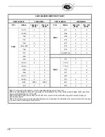
Страница 18: ... 4167 T X X 4012 X 4168 T X X 4117 X X 4169T NOTE 2 NOTE 2 5011 X X 4170 X X 5012 X X NOTE 1 Scanner and control frequency must be compatible with frequency of power line NOTE 2 For 25SU3 Model 4169T code 17 and earlier use 45UV5 Model 1101 or 1103 50HZ For 25SU3 Model 4169T code 18 and later use 45UV5 Model 1000 or 1010 60HZ NOTE 3 With 25SU3 2000 series controls the 120 VAC to the scanner must b...

Страница 19: ...lter UV 4 Measure voltage across scanner terminals Between terminals 14 and C there should be 70 VAC pulses of 6 microseconds use oscillo scope Between terminals L and C there should be 200 to 250 VAC for units manufactured before 1994 For later units there should be 130 to 150 VAC 5 Scanner operation can be checked by aiming the scanner at a source of ultra violet radiation lighter or propane tor...

Страница 20: ...h is found defective in material or workmanship or which otherwise fails to conform to the description of the product on the face of its sales order THE FOREGOING IS IN LIEU OF ALL OTHER WARRANTIES AND FIREYE MAKES NO WARRANTY OF MERCHANTABILITY OR ANY OTHER WARRANTY EXPRESS OR IMPLIED Except as specifically stated in these general terms and conditions of sale remedies with respect to any product ...

Отзывы: