13
MAINTENANCE
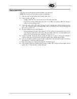
CAUTION: Disconnect or shut off electric power when working on scanner.
1.
The Fireye (25SU3 or 25SU5) control and scanner should be powered at all times (except for
repair, cleaning or replacement) to reduce any harmful effects of atmospheric humidity.
2.
The scanner and sight pipe must be kept clean to prevent overheating and assure optical quali-
ties.
3.
When replacing or cleaning the UV tube, note the position of the tube electrodes in relation to
the rectangular slot in the shutter assembly. Replace tube in the same slot location.
4.
Clean the quartz lens with glass detergent or glass cleaning agents which contain no abrasives.
After cleaning remove all cleaning films with a soft lint-free cloth.
5.
Use original Fireye repair parts to maintain optimum operation
CONTROL AND SCANNER WIRING
All wiring to the scanner should be rated at 600 volts and 90
C. For runs less than 1000 feet Fireye
recommends the use of scanner cable Part No. 59-470 (4 conductors 18 AWG, 2 conductors 22
AWG, common shield) or Part No. 59-471 (4 conductors 18 AWG, 4 conductors 22 AWG, common
shield). For runs in excess of 1000 feet, consult the factory. For ease of installation and occasional
service, the wires should be routed to the screw terminals in the scanner via a flexible conduit per the
following groups. Always refer to the appropriate flame safeguard control bulletin.
Group I Fireye Controls
A blocking diode, Fireye Part Number 101-78, must be used when a solid state type scanner is used
in parallel with a UV scanner. Connect the diode in series with the lead from terminal 14 in the UV
scanner as shown in Figures 16 and 20. This is to avoid damaging the solid state scanner. If the appli-
cation requires that only one scanner be in use at any time, the other unit can be removed from oper-
ation by breaking the power lead (LA or LB).
Group II Fireye Controls
If the intended use requires that the amplifier input signal come from one of two or more scanners,
the power and shutter drive signals should be switched between scanners using a single relay “S” or
selector switch. This permits the operation of one scanner at a time. As with Group I amplifiers, the
blocking diode is necessary when using the solid state scanner with a UV unit (see Figure 17).
RECOMMENDED SPARE PARTS
FIGURE
PART NUMBER
DESCRIPTION
Engineering Code
00-03 (Through
mid- 2008)
Engineering Code
04 and 05
(2008 to 2012)
Engineering Code
06 and higher
(July 2012)
12A
4-320-1
4-290-2
4-314-1
UV Tube
12B
61-2914-1
61-2914-1
61-2914-1
Shutter & Bracket Ass'y.
12C
61-2913-1
61-7203
61-7203
Shutter, Bracket, and Lens Ass'y. (includes 61-2914-1).
12D
29-248
29-248
29-248
Flange Gasket
12E
82-95
82-95
82-95
Lens Holder
12F
16-103
16-103
16-103
Lens Retainer (grommet)
13L
46-38
46-179
46-179
Lens
12G
61-2275-2
61-2275-4
61-2275-4
Lens Assembly (includes Holder, Retainer, and Lens)
13M
92-48
92-48
92-48
Quartz Window (Part of Sealing Coupling 60-1199-x)


