12
HotPort Series 6000 Mesh Nodes
Mounting the Universal Bracket
The HotPort enclosure should be mounted securely. You can mount the enclosure to a wall, a light pole, or an irregularly shaped pole. The
universal mounting bracket has been designed with multiple holes and slots to allow mounting with bolts, straps, or other methods. Extra
nuts and bolts are provided for this purpose; don’t be alarmed if you have leftover fasteners when installation is complete.
Removing the Bracket
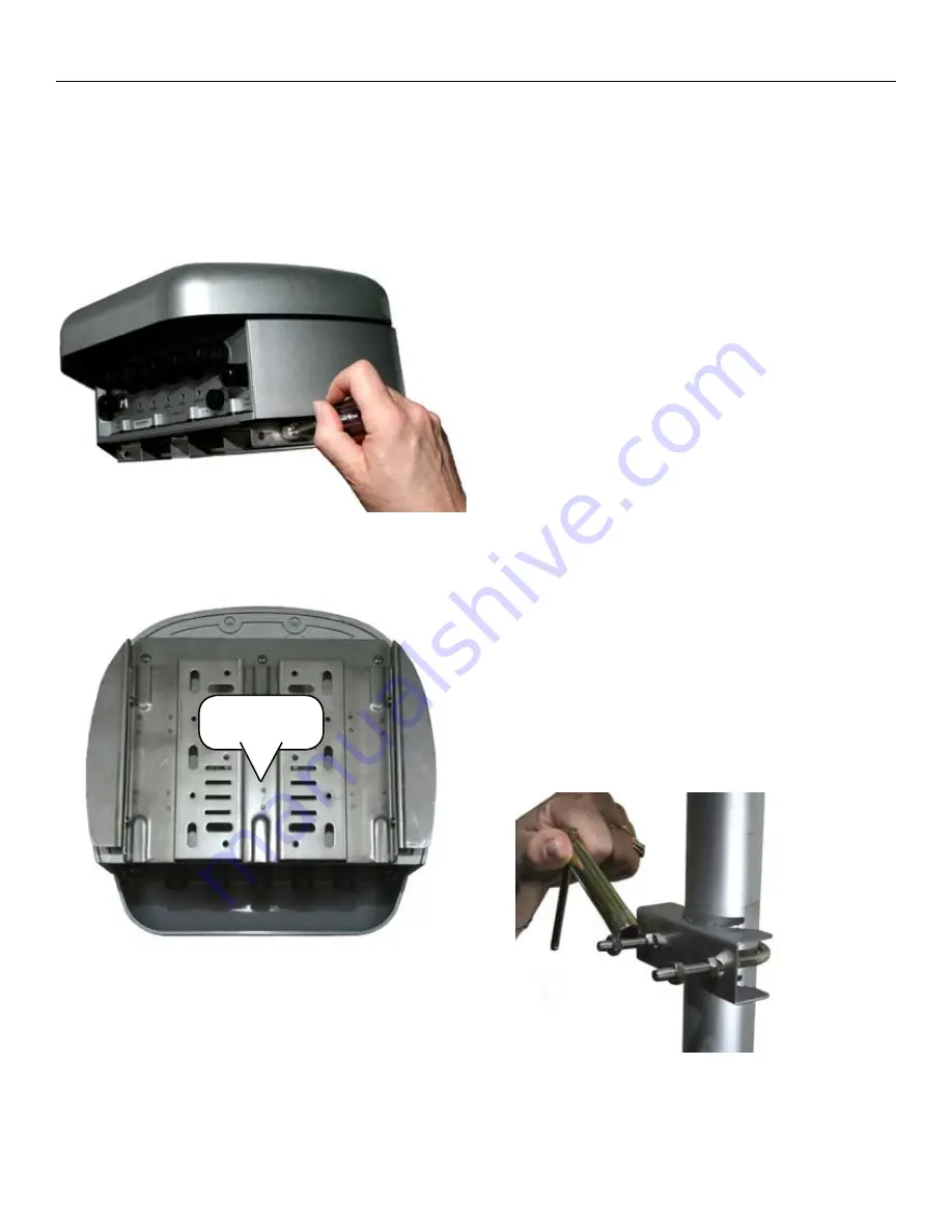
The bracket is shipping already attached to the HotPort node. Begin
by removing it. This is done by loosening the four Phillips screws,
two on each side, as shown in Figure 13.
Figure 13. Removing the Mounting Plate
Next, slide the plate down, toward the connector side of the HotPort
node, as shown in Figure 14. This releases its tabs from the node
itself.
Figure 14. Sliding the Mounting Plate Off
Next, you will attach the Universal Mounting Plate to your chosen
mounting location.
Slide the plate
down
Choosing a Mounting Location
For best results, provide clear line-of-sight access for the an-
•
tennas. You can test various locations by mounting the unit to
a portable stand until you can determine the ideal location for
permanent mounting.
The location must allow for a solid connection to earth ground.
•
Be sure the ground does not obstruct access to the enclosure.
The unit must be within reach of the power cord. A five meter AC
•
cord is provided, or a DC cord may be used.
Wall Mounting
The Universal Mounting Bracket contains holes and slots to allow it
to be mounted via U-bolts or straps. Use four screws (not supplied)
to attach the universal mounting bracket securely to the wall using
the four holes near the top and bottom of the universal mounting
bracket. Use appropriate anchors when attaching to masonry or
other materials.
Pole Mounting
You can mount the HotPort node to a 37 mm to 50 mm (1.5” to 2”
pole using the supplied U-bolts. Your installation kit includes a small
T-handle socket wrench which fits the supplied nuts.
Insert the two U-bolts through the holes in the claw-toothed
1.
pole-gripper piece.
On each U-bolt, place a washer, a lock washer, and a nut, as
2.
shown in Figure 15. Smaller pole diameters usually require a
second nut as a spacer to hold the bracket away from the U-bolt
clamp. Finger-tighten the nuts. Figure 15 shows this second
nut, as a spacer. There should be about 12-15 mm (1/2-5/8”) of
U-bolt sticking past the second nut.
Figure 15. U-bolt Mounted on Pole
January 2009


