Firetide. Reliable Connectivity Anywhere
3
Preliminary Version 1.1
Using the Mounting Bracket
The bracket allows easy tilting and aiming of the device. It also allows the unit to be mounted with
its internal antenna oriented for either vertical or horizontal polarization and allows mounting on
either a horizontal or vertical pole. Note that the internal antenna polarization is vertical when the
connectors are pointed down. A 2.4 GHz antenna is built in to the unit. There is also an external
antenna connector. Keep the plastic cover on this connected to prevent water from getting into
the unit.
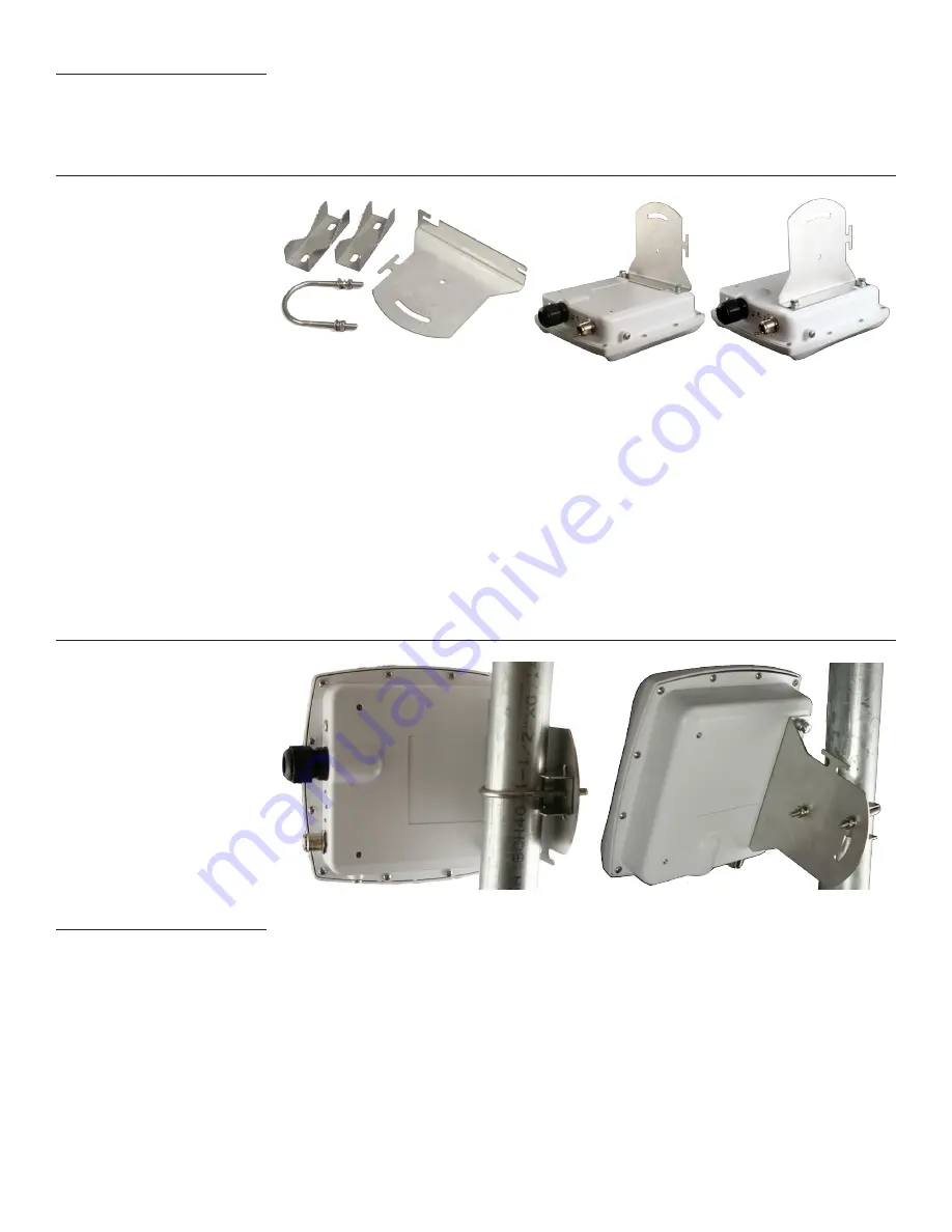
Figure 2. FWB-100 Mounting Bracket
In order to avoid climbing up and down the pole twice, power up the unit before proceeding with
the installation. The only connection you need is the Ethernet; it provides power as well.
Attach the bracket to the back of the unit, using the two slotted holes shown on the right side of
the bracket, as shown in Figure 2. Select two holes on the unit according to the desired orientation
of the pole and the antenna.
The bracket is attached to the pole using the U-bolt and one or two of the supplied jaw-clamps
(Figure 3). One jaw-clamp is used between the bracket and the pole; the second clamp may be used
on smaller-diameter poles by placing it over the U-bolt before putting the U-bolt around the pole.
After placing the U-bolt around the pole, place the bracket over the legs of the U-bolt such that
one leg passes through the round hole and the other leg passes through the curved slot. Snug the
bracket slightly with the supplied nuts and lockwashers, but do not tighten until you have aligned
the unit. The result should resemble Figure 3.
Figure 3. U-bolt Mounting Assembly; Tilting the Unit for Signal Alignment
Aligning the FWB
The Alignment LED provides a visual indication of signal strength. Point the FWB in the direction
of its signal source, then carefully adjust it, both horizontally and vertically, using the Alignment
LED as a guide. The LED will blink more rapidly as the signal strength increases. When you receive
the strongest signal, tighten the nuts. Figure 3 shows how the bracket can be used to tilt the unit.
The LED alignment feature is enabled by default. To insure maximum performance, you should dis-
able the feature via the web interface after installation is complete. If you are re-aligning anten-
nas, be sure to re-enable the alignment feature.


