background image

   Firetide FWB-100 Wireless Bridge User Guide 

August 2010 

Chapter 1.  Setting Up Your Equipment 

Introduction

  The  Firetide  FWB-100  wireless  bridge  provides  wireless  point-to-point  connectivity  for  Ethernet 

traffic, indoors or out. The FWB-100 is sold in pairs, which have been programmed at the factory to 
work with each other. Installation of the devices should only be done by qualified and experienced 
personnel. Outdoor installation involves many safety hazards, including electrocution, lightning 
strikes, and falls. Please be careful.

Unpacking and Setup

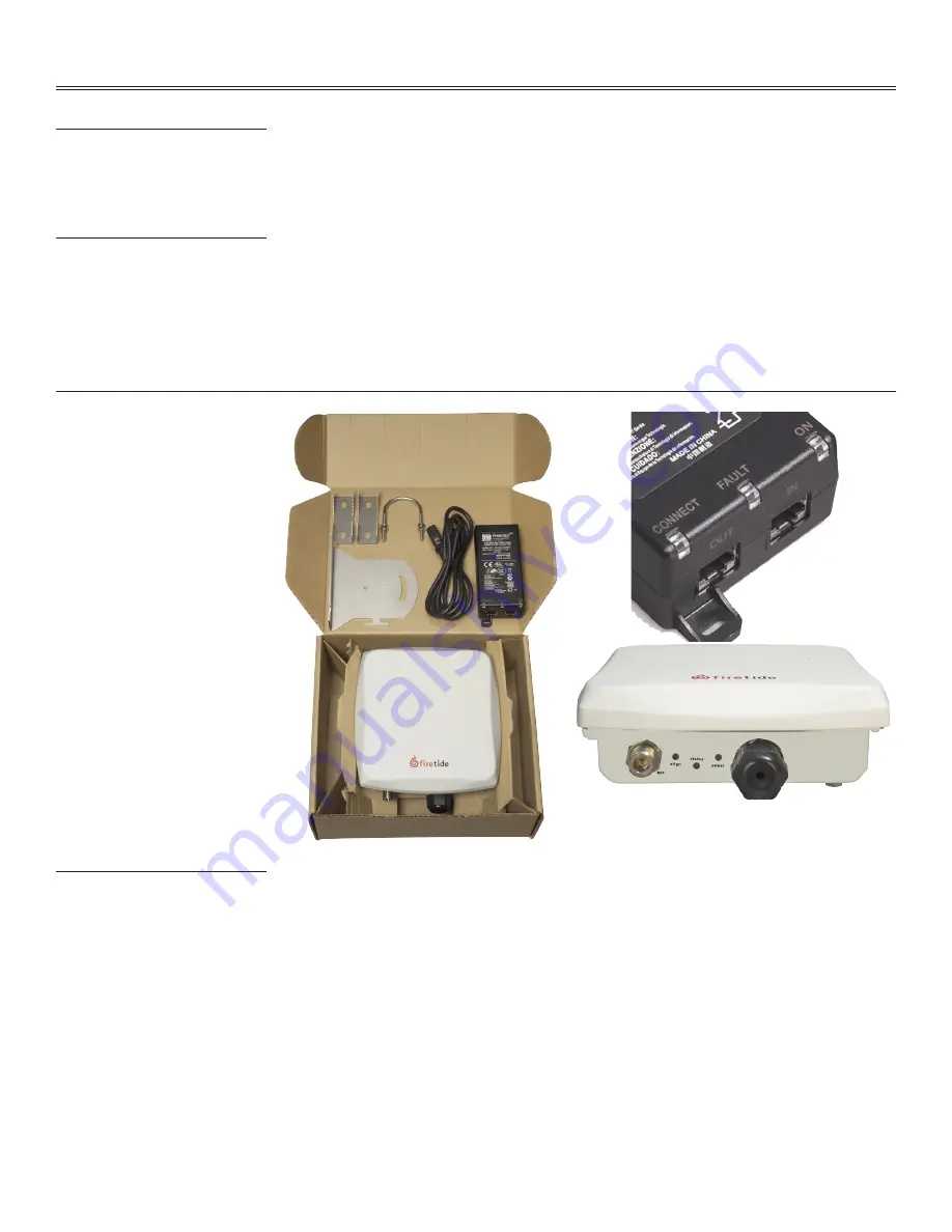
  A basic FWB-100 is shown in Figure 1. In addition, the FWB is offered as the FWB-102, a pair of 

units designed to use the integrated 2.4 GHz antenna built into the bridge. The FWB-105 is a pair 
of units including two external antennas designed for 5 GHz. (Note: If you are using a 5 GHz an-
tenna, you must set “Select Active Antenna” to “Antenna 2 (external)”.)


Note that an Ethernet cable is NOT included. You should obtain a weatherproof 4-pair cat-5 cable 
long enough to reach from the unit to the location where you will connect with other equipment. 
The cable must be a 4-pair cable; smaller cables will not seal in the waterproof connector. The 
cable can be pre-terminated; the waterproof connector will pass an RJ-45 plug.

Figure 1.  FWB-100 Package Contents; Power Injector & Connectors

Assembling the Ethernet Cable

  Test the unit before mounting it on the pole or mast. Begin by making the cable.

1. Remove the weatherproof Ethernet connector cover - the black plug - from the unit.
2. Dismantle it. You will have a housing, a housing insert, a cap, and a gasket.
3. Place the cap over one end of your Ethernet cable.
4. Place the housing insert over the cable.
5. Thread the cable through the housing.
6. Plug the cable into the RJ-45 port visible inside the unit.
7. Thread the housing back into the unit. Make sure the gasket is still in place.
8. Tighten the cap so that it compresses the housing insert to the housing.


Now you can connect the Ethernet cable to the power feed unit, via the OUT port on the power 
feed unit. The CONNECT light should turn green. If the FAULT light comes on, contact Firetide. The 
Firetide device needs about two minutes to boot itself. When it completes this process, the Status 
will turn green.

Содержание FWB-100

Страница 1: ...7 Preliminary Version 1 1 The contents of this User Guide are subject to change without notice Please refer to the Firetide partners web site partners firetide com for current versions User Guide FWB 100 Wireless Bridge ...

Страница 2: ...rom the unit to the location where you will connect with other equipment The cable must be a 4 pair cable smaller cables will not seal in the waterproof connector The cable can be pre terminated the waterproof connector will pass an RJ 45 plug Figure 1 FWB 100 Package Contents Power Injector Connectors Assembling the Ethernet Cable Test the unit before mounting it on the pole or mast Begin by maki...

Страница 3: ...t and one or two of the supplied jaw clamps Figure 3 One jaw clamp is used between the bracket and the pole the second clamp may be used on smaller diameter poles by placing it over the U bolt before putting the U bolt around the pole After placing the U bolt around the pole place the bracket over the legs of the U bolt such that one leg passes through the round hole and the other leg passes throu...

Страница 4: ...odes are paired or married at the factory Within each pair the unit with the lower serial number is assigned IP address 192 168 224 161 and the unit with the higher serial number is as signed IP address 192 168 224 162 You can change these addresses if desired Configure the computer to have an IP address on the subnet 192 168 224 0 24 When you power up the two units on the bench they will usually ...

Страница 5: ...0 to 9 miles 0 to 14 5 km Click Apply to save settings Link Basic Settings Link Basic Settings include Multicast Data Rate Fragmentation Threshold and Management VLAN Settings The data rate can be set from 1 Mbps up to 54 Mbps Fragmentation threshold is gener ally left at the default setting of 2346 Management VLAN status can be enabled or disabled When enabled select the appropriate management VL...

Страница 6: ... Radio Settings Radio settings used by the node are displayed on this page Node settings for Modulation Data Rate and Transmission Power can be selected Click Apply to save settings Advanced Radio Settings Advanced radio settings allow you to select the active antenna If you are using an external 5 GHz antenna e g you purchased the FWB 105 package you must set Select Active Antenna to External Ant...

Страница 7: ...g Save Nodes can be restored by using the Restore function to apply a previously saved file System Commands System Commands let you reboot the Appliance or perform a factory reset Note that a factory reset will re enable the antenna alignment tool and require you to re specify the country code Antenna Alignment Antenna alignment settings are available here Alignment is on by default To insure maxi...

Страница 8: ...Refresh to see the current status Link status includes current radio operating mode RF channel node MAC addresses and IP addresses The Manage Remote but ton lets you connect to and manage the remote node as long as the RF link is up Node Status Node Status is displayed here Click Refresh to see the current status ...

Страница 9: ...firmware you must have Java installed on your PC When you begin this pro cess the Java applet will take a moment to load Browse to select upgrade image Click Start Upgrade to begin Once started the upgrade can be cancelled by clicking Cancel Upgrade Logout Select the Logout tab to securely exit from the session ...

Страница 10: ...9 12 18 24 36 48 54Mbps Network Standards IEEE 802 11a b d g e f h i Transmit Power Control TPC capable in conjunction with Firetide Software application Security Encryption WPA 64 128 256 w TKIP AES IEEE 802 1x LEAP Regulatory Certifications Contact your Firetide dealer for product availability and certifications for your country Specification FWB 102 FWB 105 Network Port One 10 100 Mbps Ethernet...

Страница 11: ...cuit different from that to which the receiver is connected Consult the dealer or an experienced radio TV technician for help FCC Radiation Exposure To ensure compliance with the FCC s RF exposure limits the antenna used for this transmitter must be installed to provide a separation distance of at least 70 cm from all persons and must not be co located or operated in conjunction with any other ant...

Страница 12: ...ct to change without notice Firetide HotPort and HotPoint are registered trademarks of Firetide Inc Reliable connectivity anywhere HotView HotView Pro MeshBridge and AutoMesh are trademarks of Firetide Inc In no event will Firetide be liable for any special incidental consequential punitive or indirect damages whatsoever including without limitation damages for loss of profits business interruptio...

Отзывы: