fp_22408_m4.1
Page 4 of 10
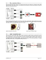
Mount the Internal Activation Switch in a dry, protected area (such as the vehicle cab). It should be clearly visible
and within reach of the vehicle operator. This should then be connected to the control panel using one of the two
Detection Circuits (marked Green).
Mount the External Activation Switch on the exterior of the vehicle. This should be easily accessible and away from
the risk area.
Note:
the supplied End of Line module MUST be plugged into the cables coming out of the Internal
Activation Switch if no External Activation Switch is to be used.
Switch mechanism with travel Pin
Switch Shown in External Mount
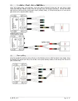
Mount the Linear Heat Detection Cable inside the risk area using the supplied P-clips every 500mm and junction
boxes. With reference to use one of the supplied 2 Pin Deutsch Plug pairs create a extension cable and plug into
the remining Detection Circuit (marked Green). This kit comes with an installed End Of line resistor that must be
installed at the end of the LHD cable.
Note:
wiring should not be done in a way that place tension on the cable
and installers MUST observe the minimum bend radius on 150mm.


