


14
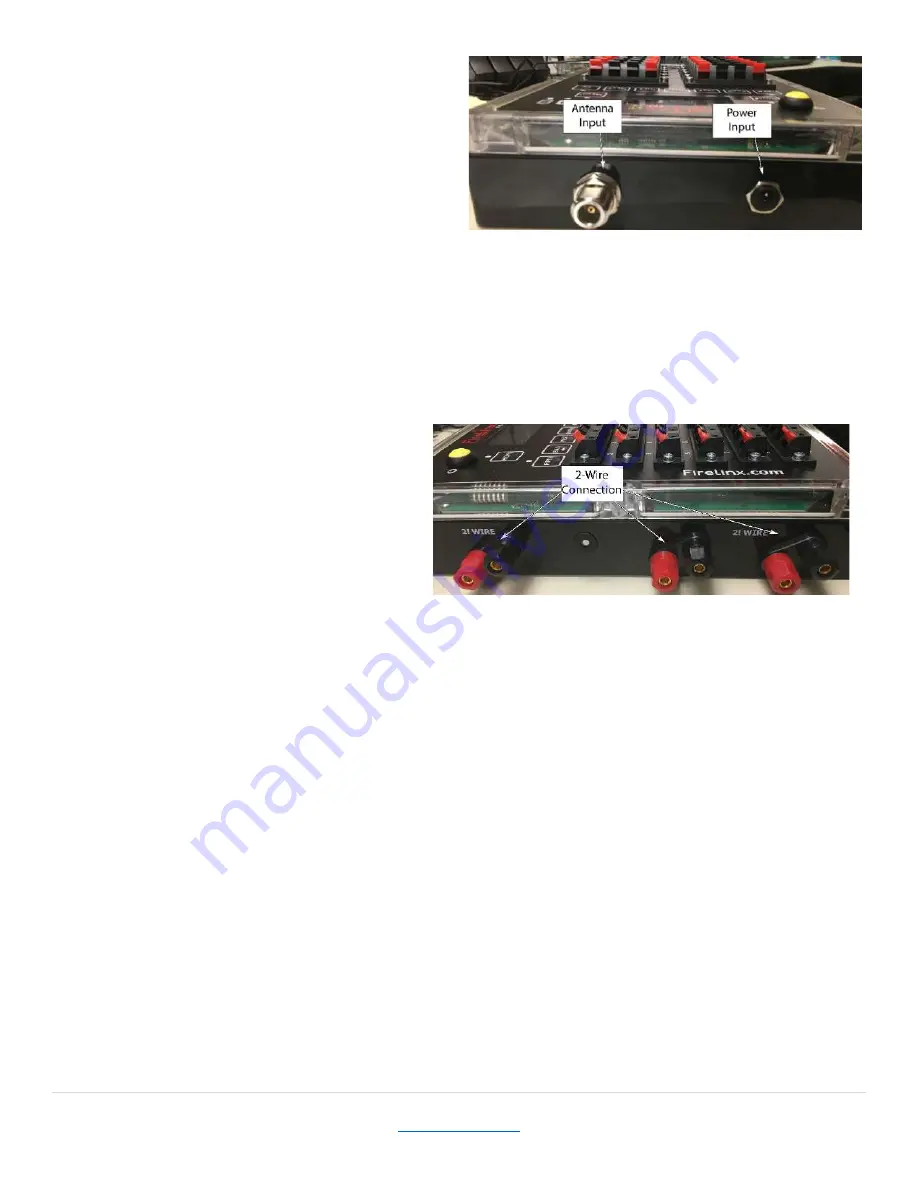
Power Input
This port is used for charging the FM.
Tech Specs of Port: 5.5mm OD 2.0 mm ID
such as the Switchcraft S760 center positive,
outer negative, 12 volts max 1 Amp.
In an emergency (dead battery), a 12V power
supply or high current battery such as lead
acid can be connected to this port. It will
need to produce at least 2A of current
during the Arming process, so a standard wall-wart transformer will not be sufficient.
Antenna Input
For shows that require wireless communication, screw in the radio antenna here. We
recommend that the antenna always be installed as backup communications even if the 2-Wire
system is connected.
For greater signal strength, raise the height of the unit so that the antenna is at least 8 inches
off the ground.
2-Wire
These terminals are used for 2-Wire
communications between the CM and
FMs. FMs can be daisy-chained or
connected in a star formation. Standard
22-24Ga scab wire can be used and it
does not matter which conductor is
attached to which terminal. We recommend that in order to make it easy to check for mis-wired
connections, connect the incoming wire to the single terminal pair, and then connect one or two
outgoing wires to the other terminal pairs. Daisy Chain wiring would be one wire in and one wire
out, where Star configuration is one wire in and two wires out. Any combination of Daisy-chain
and Star is allowed.
Firing Module Basic Setup
1.
Turn on the System
- Press and hold the power button. Lights will turn on and the screen will
light up. A logo splash screen will appear and then the Home screen. The system is now
ready.
2.
Joining CM –
To join FMs to the CM, on the CM go to MENU->(3): JOIN. On the FM press the
MENU key, and use the up and down arrow keys to select JOIN MODE. Press Enter. If the
numbers displayed on the CM and FM match, press YES to join them together. If the numbers
do not match, then the FM is trying to join a different CM. Press the NO button, and the FM
will display the ID of the next CM in the area. Continue until your CM is listed. If no numbers
are displayed the CM and FM might not be on the same RF channel. The RF channel can be set
manully by selecting the RF Channel option in the MENU. The Wireless Wizard function in the
CM can only change the RF Channels of FMs already joined and communicating.
Figure 20
Figure 19


