


Page 7
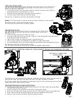
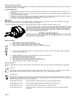
Using the Boom Nozzles
Four things must be considered before spraying with the boom.
How much chemical must be mixed in the tank.
Rate of spray (gallons per acre to be sprayed).
What pressure (p.s.i.) will be used.
Speed traveled (mph) while spraying.
Refer to the chemical label to determine your chemical mixture
See the tip chart to determine the pressure to be used. The chart will also show the speed used when spraying.
Start the pump and open the valve to the boom nozzles.
Check the spray pattern. Usually you can see the coverage better on a solid concrete surface, such as a driveway.
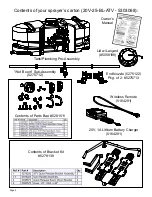
Approximate height: 33”
Maintenance During/After Spraying
Periodically check the strainer and clean the screen on your intake line.
Proper care and maintenance will prolong the life of your sprayer.
After use, drain the tank and store or dispose of chemical properly. Fill the sprayer half way with clean water. Start the pump and allow the water to
pump through the entire plumbing system and nozzles. Drain and then refill half full, add the recommended amount of a good quality tank cleaner,
such as FIMCO Tank Neutralizer and Cleaner. (If no tank cleaner is available, you may substitute dish soap for this step, about 1-2 oz. per gallon).
Turn pump on and circulate through system for 15 minutes and then spray out through boom and handgun nozzles. Refill sprayer half way with clean
water and repeat. Follow the chemical manufacturer’s disposal instructions of all wash or rinsing water.
If boom or handgun nozzles need cleaning, remove them from the sprayer and soak in warm soapy water. Clean with a soft bristled brush or toothpick
if necessary. Never use a metal object. Even the slightest damage can change the flow rate and spray distribution. Water rinse and dry the tips before
storing.
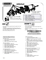
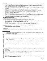
WARNING:
Some chemicals will damage the pump valves if allowed to soak untreated for a length of time! ALWAYS flush the pump as
instructed after each use. DO NOT allow chemicals to sit in the pump for extended times of idleness. Follow the chemical manufacturer’s
instructions on disposal of all waste water from the sprayer.
Winter Storage
Prepare the sprayer for end-of-season storage by running RV
antifreeze through the system. This will keep internal parts
lubricated, protect against corrosion and keep the unit from
freezing.
Note: RV antifreeze is non-toxic and biodegradable
and generally safer for the environment than automotive anti-
freeze.
Before storing your sprayer for winter or long term storage,
thoroughly clean and drain it as much as possible. Then pour
enough pink RV antifreeze into the tank so that when the pump
is turned on you can pump the antifreeze throughout the entire
plumbing system, including the bypass. Make sure to operate
the boom and handgun until you see pink fluid spraying from
the nozzles. Leave any remaining antifreeze in the tank. Be-
fore your next usage, rinse the antifreeze from the sprayer with
clean
water.
It is nearly impossible to drain all of the water from the sprayer
and any trapped water can freeze in cold weather and damage
parts of the sprayer. Pumping the antifreeze through the sys-
tem will displace the water and help prevent this damage.
Removing from storage: drain the antifreeze. Fill the tank with
fresh water and run through the system. Dispose of antifreeze
and flush water properly.
Rate Chart for Boomless Nozzle (Set of 3)
Gallons per Acre Based on Water - 17-1/2" Spacing
Pressure
P.S.I.
Capacity
G.P.M.
(3 Nozzles)
1 MPH 2 MPH 3 MPH 4 MPH 5 MPH 6 MPH 8 MPH
20
1.68
28.0 14.0
9.4
7.0
5.6
4.7
3.5
30
2.05
34.4 17.2 11.4
8.6
6.9
5.7
4.3
40
2.40
'39.6 19.8 13.2
9.9
7.9
6.6
5.0
Gallons per 1000 Sq. Ft. Based on Water - 17-1/2" Spacing
Pressure
P.S.I.
Capacity
G.P.M.
(3 Nozzles)
1 MPH 2 MPH 3 MPH 4 MPH 5 MPH 6 MPH 8 MPH
20
1.68
0.64 0.32 0.21 0.16
0.13
0.11 0.08
30
2.05
0.78 0.39 0.26 0.20
0.16
0.13 0.10
40
2.40
0.90 0.45 0.30 0.23
0.18
0.15 0.12
Gallons per 100 Sq. Ft. Based on Water - 17-1/2" Spacing
Pressure
P.S.I.
Capacity
G.P.M.
(3 Nozzles)
1 MPH 2 MPH 3 MPH 4 MPH 5 MPH 6 MPH 8 MPH
20
1.68
0.064 0.032 0.021 0.016 0.013 0.011 0.008
30
2.05
0.078 0.039 0.026 0.020 0.016 0.013 0.010
40
2.40
0.090 0.045 0.030 0.023 0.018 0.015 0.012
** The rate of spray as shown in the chart will remain the same with 1, 2 or 3 Nozzles **
The only difference will be with the width of the spray swath
Speed Chart
Time Required in seconds
to travel a distance of
Speed in M.P.H.
(Miles Per Hour)
100 Ft.
200 Ft.
300 Ft.
1.0
68 sec.
136 sec.
205 sec.
2.0
34
68
102
3.0
23
45
68
4.0
17
34
51
5.0
14
27
41
6.0
11
23
34
7.0
9.7
19
29
8.0
8.5
17
26
9.0
7.6
15
23
10.0
6.8
14
20
Quarter turn at a time clockwise until surging stops
Check that shut-off valve on inlet (if applicable) is open
Pump continues to run:
Bypass (if applicable) is not completely closed
System has leaks
Check for worn or dirty check valve
Fuse blows:
Excessive voltage
Improper adjustment of pressure switch
Defective pressure switch
Pump surges:
Low flow may cause pump to surge
Spray wand is adjusted for a small or fine spray pattern
Slightly open bypass (if applicable) to overcome
If needed, pressure switch may need to be adjusted
Check for defective pressure switch
Low Pressure/Low Flow:
Check for a clogged strainer
Check for proper voltage
Check for worn or dirty check valve
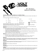
Troubleshooting
Pump will not run:
Check for loose wiring
Make sure the ON/OFF switch is on
Check the fuse