background image


HIGH LEVEL INTERFACE 


UL S3217 

P/N 06-158 

FM 3020297 


Rev 5, 02/2015


3.0 INSTALLATION 

The HLI should not be installed until after all construction cleanup has been completed in order to avoid any 
potential damage to the electronics due to dust and debris.  Before installing the HLI assembly into the 
enclosure, thoroughly clean the enclosure to remove any dirt, dust and debris. 

3.1 MOUNTING 

LOCATION 

The mounting location for the HLI is very important.  The HLI must be located in the same room and within 50 
feet (15 m) of the host control panel.  The following guidelines shall be considered when selecting the 
mounting location for the HLI: 

1.  Locate the HLI enclosure in an area that is readily accessible with sufficient room to allow easy 

installation and maintenance. 

2.  The room shall be capable of maintaining a nominal temperature of 32

°

 - 120

°

F (0

°

 - 49

°

C) with a 

relative humidity of 93%. 

3.  Additional items to consider when selecting the mounting location shall include:  vibration, dust, 

moisture, electromagnetic interference, and radio frequency interference. 

All of the items listed above could adversely effect the successful operation and useful life of the HLI 
electronic components and should be avoided if possible. 

3.2 ENCLOSURE 

INSTALLATION 

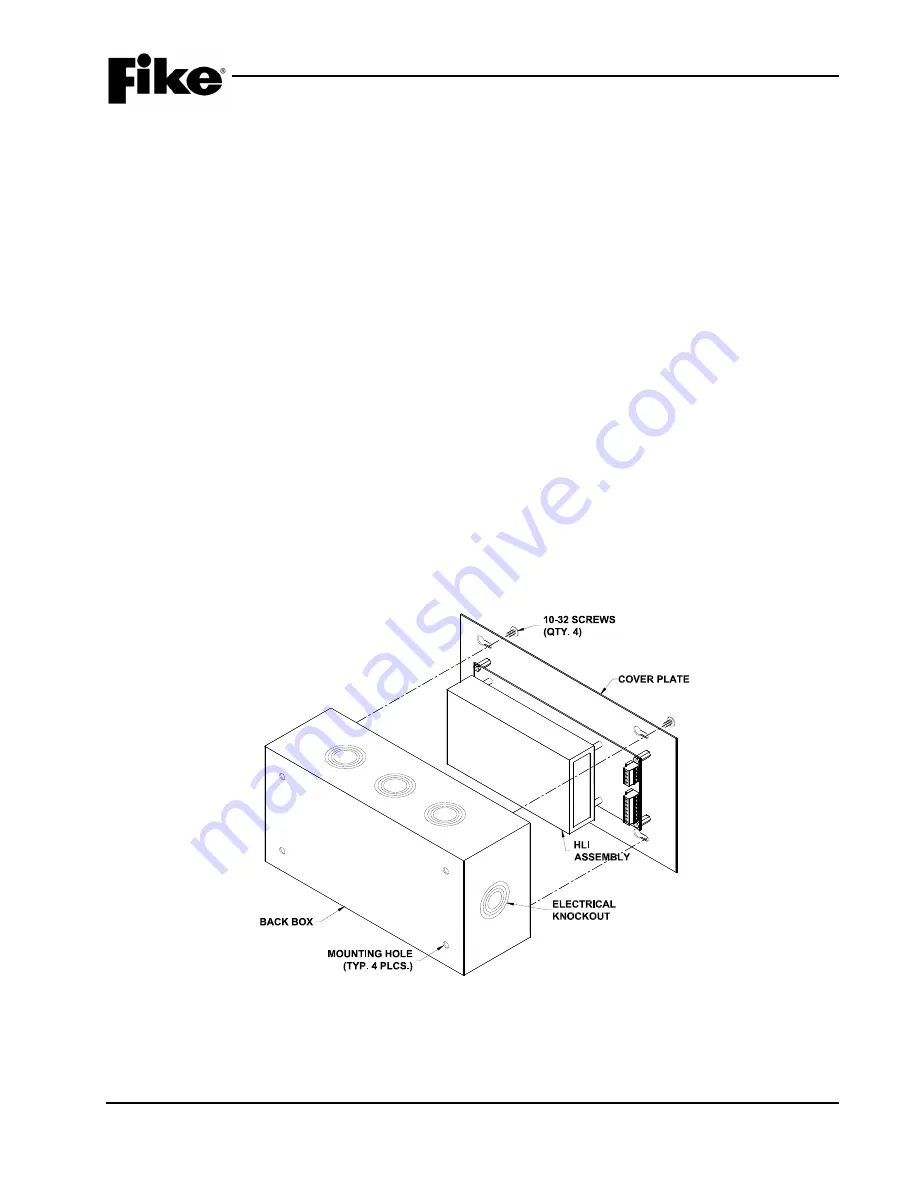
The HLI enclosure is equipped with four mounting holes in the back box that allows surface mounting of the 
box to the wall surface (See Exhibit 5).  The mounting holes are spaced at 10 inch (25.4 cm) horizontal 
centers and 4 inch (10 cm) vertical centers. 


The back-box is equipped with conduit knockouts on all four sides that allows easy access into the box for 
electrical connections to the HLI. 


Exhibit 5:  Enclosure Installation 

Содержание 68-023

Страница 1: ...Product Manual P N 06 158 Rev 5 February 2015 P N 68 023 HIGH LEVEL INTERFACE HLI VESDAnet Interface...

Страница 2: ...urned from an authorized Fike Distributor Contact Fike s Marketing department for further warranty information Fike maintains a repair department that is available to repair and return existing electr...

Страница 3: ...I Wiring 10 3 4 VESDAnet Wirng 13 4 0 Configuration 14 4 1 Cheetah Configuration of VESDA Units 14 4 2 CyberCat Cheetah Xi Configuration of VESDA Units 16 5 0 Operation 19 5 1 Silence and Acknowledge...

Страница 4: ...heetah Fire 1 Level 25 24 Cheetah Fire 2 Level 26 25 CyberCat Cheetah Xi Alert Level 26 26 CyberCat Cheetah Xi Alert Level Details 27 27 CyberCat Cheetah Xi Alert Clear 27 28 CyberCat Cheetah Xi Actio...

Страница 5: ...Date Reason for Change 0 All Sections 10 2003 Initial Release 1 All Sections 09 2004 Updates to Firmware Manual Format Corrections 2 All Sections 03 2007 Include Operation with CyberCat and Cheetah X...

Страница 6: ...art Number Cheetah Installation Operation and Maintenance Manual 06 148 CyberCat 254 1016 Addressable Fire Alarm Product Manual 06 326 Cheetah Xi Addressable Fire Suppression Product Manual 06 356 Cyb...

Страница 7: ...tector manual fire alarm box or supervisory switch This manual interchanges the terms initiating device and input device Initiating Device Circuit A circuit to which automatic or manual initiating dev...

Страница 8: ...ore installing or using this device Accidental damage to the device could result if these warnings and cautions are not heeded aWARNING Failure to disconnect power to the releasing circuit s and compl...

Страница 9: ...control panel with firmware V4 20 or higher up to 40 VESDA detectors can be connected to the HLI If using a VESDA HLI with firmware older than V3 08 0 0 or a host control panel with firmware older th...

Страница 10: ...l or Ground fault could result Wiring 16AWG minimum THHN Terminal block accepts 12 AWG 16 AWG P9 A A Shield B B Shield VESDAnet Incoming Outgoing RS485 Non power limited Supervised 120 impedance shiel...

Страница 11: ...easy installation and maintenance 2 The room shall be capable of maintaining a nominal temperature of 32 120 F 0 49 C with a relative humidity of 93 3 Additional items to consider when selecting the...

Страница 12: ...m of the panel and must be powered from the host control panel s 24VDC continuous auxiliary output Refer to Exhibits 6 7 and 8 for wiring diagrams showing how to wire the HLI to each control panel 24V...

Страница 13: ...CYBERCAT 254 1016 CONTROLLER 24VDC 24VDC OUT TO NEXT DEVICE SHIELD WIRE 24V VESDA PC Link HLI P10 P9 0V 24V 0V V netA V net A SHLD V netB V net B SHLD SHIELD WIRE VESDAnet IN VESDAnet OUT RS232 CABLE...

Страница 14: ...02 11544 REV A F1 F2 F3 F6 F5 F4 24VDC 24VDC OUT TO NEXT DEVICE SHIELD WIRE 24V VESDA PC Link HLI P10 P9 0V 24V 0V V net A V net A SHLD V net B V net B SHLD SHIELD WIRE VESDAnet IN VESDAnet OUT RS232...

Страница 15: ...VESDANET WIRING The HLI can be connected at any point on the VESDAnet network within 4265 ft 1300 m of the VESDA devices it is wired to See Exhibit 9 LNote When connecting nodes in the VESDA network a...

Страница 16: ...VESDA zones the zone number configured at the VESDA is referenced in Cheetah with the word UNIT 4 1 2 CONFIGURATION SCREENS The LCD screen to configure a VESDA is accessed via the same path as with an...

Страница 17: ...heetah zone assigned to pipe sector 4 D17 D18 Pre discharge participation for the Fire 2 alarm level Select AL for alarm only SU for Supervisory TR for Trouble or PD to participate in pre discharge de...

Страница 18: ...of the 3 fields and use the buttons to change to a different zone number Line 2 Detector type Select the type by positioning the cursor under that area and using the keys until the type detector inst...

Страница 19: ...0 0 Exhibit 17 VESDA Loop Addr Menu Line 1 VESDA Detector Zone number Arrow under the field and use the button to change the VESDA detector zone number Line 2 If using the VESDA to notify with Voice E...

Страница 20: ...ach addressable input device This selection will tell the panel how this VESDA should participate with the Suppression zone See Cheetah Xi Product Manual Appendix 4 for definition of each of these Pre...

Страница 21: ...scharge In the Cheetah Xi FIRE 1 can be programmed to participate in pre discharge FIRE 2 will also re activate the alarm state for the configured zones in the FIKE control panel and will cause the de...

Страница 22: ...oard relays change states Condition is non latching and will clear itself when obscuration level drops below the Alert Level in the VESDA Unless VESDA is set to latching on Alarms Action Level Pre Ala...

Страница 23: ...rom clearing on the control panel Since this Supervisory State is caused by VESDA Fire 1 or Fire 2 it is a latching event at the panel whether the VESDA is configured to latch on alarm or not 5 5 3 TR...

Страница 24: ...l has been silenced during the Fire 1 Level the panel LED and Piezo do NOT resound when Fire 2 Level is reached Fire 2 Level Alarm LED illuminates on panel piezo on steady and Alarm state entered for...

Страница 25: ...ate This condition is non latching and will clear when the obscuration level drops below the Alert Level in the VESDA Unless VESDA is set to latching on Alarms Action Level Trouble LED illuminates on...

Страница 26: ...0 A A L E R T 0 0 3 5 0 0 4 6 B D E V I C E C U S T O M M E S S A G C 0 4 1 7 2 6 P M 1 2 3 0 9 7 D 0 0 2 0 0 5 2 0 1 1 P 0 0 R 0 0 Exhibit 19 Cheetah ALERT Level A1 5 VESDA ALERT level activated A8 1...

Страница 27: ...hen the ACTION level clears is 1 2 3 4 5 6 7 8 9 0 1 2 3 4 5 6 7 8 9 0 A A C T I O N L E V E L R E S T O R E B D E V I C E C U S T O M M E S S A G C 0 4 2 0 0 0 P M 1 2 3 0 9 7 D 0 0 2 0 0 5 2 0 1 1 P...

Страница 28: ...RCAT VESDA ALARM LEVELS VESDA detectors have four alarm levels ALERT ACTION FIRE 1 and FIRE 2 The levels convert from VESDA to CyberCat Cheetah Xi as follows VESDA CyberCat Cheetah Xi Alert PreAlarm 1...

Страница 29: ...obscuration of the VESDA drops back down below the ALERT threshold the event will clear and the following event history message will appear A L E R T C L E A R V Z 0 0 1 C U S T O M M E S S A G E V Z...

Страница 30: ...evel activated Unit Line 2 Current live obscuration level being sent from detector This unit will update as obscuration changes at the VESDA Line 3 Time and date stamp for this event Line 4 Event numb...

Страница 31: ...this screen F I R E 1 L E V E L V Z 0 0 1 C U R R E N T 0 0 0 1 5 F T 0 2 1 5 1 9 P 1 1 1 5 2 0 0 5 E V E N T 0 0 0 9 O F 0 0 0 9 Exhibit 32 CyberCat Cheetah Xi FIRE 1 Level Line 1 VESDA FIRE 1 level...

Страница 32: ...this screen F I R E 2 L E V E L V Z 0 0 1 C U R R E N T 0 0 0 1 5 F T 0 2 1 5 1 9 P 1 1 1 5 2 0 0 5 E V E N T 0 0 1 0 O F 0 0 1 0 Exhibit 34 CyberCat Cheetah Xi FIRE 2 Level Line 1 VESDA FIRE 2 level...

Страница 33: ...6 1 1 CURRENT HISTORY MESSAGES Should the RS 232 cable connected to the HLI become disconnected the following history message appears 1 2 3 4 5 6 7 8 9 0 1 2 3 4 5 6 7 8 9 0 A V E S D A C O M M U N E...

Страница 34: ...E S T O R E B B O A R D L E V E L E V E N T C 0 4 1 7 2 6 P M 1 2 3 0 9 7 D E V T 0 0 3 0 0 3 C U R Exhibit 38 Cheetah Event Restored LCD lines B C and D are of the same format as for Exhibit 9 2 abo...

Страница 35: ...R K F A U L T V Z 0 0 1 C U S T O M M E S S A G E V Z 0 0 1 0 9 2 5 2 2 A 1 1 1 5 2 0 0 5 E V E N T 0 0 1 5 O F 0 0 1 5 Exhibit 41 CyberCat Cheetah Xi Trouble Restore Line 1 VESDA Detector no longer c...

Страница 36: ...4 5 6 7 8 9 0 A 2 0 1 1 V E S D A 0 0 0 5 0 B U N I T 0 0 1 L E V E L N O R M C F A U L T S M M I S Z U P N A F D N N Y N N N N N N N Exhibit 43 Cheetah VESDA Levels A1 Loop number selection Range is...

Страница 37: ...is to emulate the function of the Isolate switch of the VESDA display unit When a VESDA is placed in the Isolated condition a trouble event for every zone assigned to the selected VESDA device is rec...

Страница 38: ...line 1 LNote For complete list of possible messages that could display on CyberCat or Cheetah Xi screen as well as possible causes and solutions refer to Appendix 2 Event Messages of this manual and t...

Страница 39: ...a de isolate command on the VESDA and not a reset can take the VESDA device out of the isolated condition I S O L A T E F A U L T V Z 0 0 1 C U S T O M M E S S A G E V Z 0 0 1 0 2 2 7 4 1 P 1 1 1 5 2...

Страница 40: ...reached the ACTION level 2nd level The ACTION threshold is xxx The current obscuration is yyy Locate the detector by using the address and the custom message on the 2nd line and the address on the 4th...

Страница 41: ...onnected Is RS232 Cable connected to Cheetah P3 Jack 3 Make sure the cable is connected and the HLI is powered VESDA COMMUN RESTORE Intelligently interfaced VESDA High Level Interface HLI has become r...

Страница 42: ...lear None VESDA FAULT SYSTEM VESDA Detector Trouble Corresponds with the VESDA Display fault LED Most VESDA faults will also be followed by a Fault ID The VESDA manual provides troubleshooting for the...

Страница 43: ...e on the 2nd line and the address and obscuration of the device by pressing F1 on the display Determine cause for elevated obscuration FIRE 2 LEVEL VZ nnn The VESDA detector programmed as Zone nnn has...

Страница 44: ...ached the ACTION level Locate VESDA nnn determine area for sector x Look for obvious signs of obscuration smoke SECTOR ALERT CLEAR The VESDA detector that previously reported a SECTOR ALERT event has...

Страница 45: ...DA MISSING VZ nnn VESDA detector Zone nnn is programmed in the CyberCat but not reporting through VESDAnet attached to HLI through P4 Locate VESDA nnn and determine why it is not reporting through VES...

Страница 46: ...HIGH LEVEL INTERFACE 44 P N 06 158 UL S3217 Rev 5 02 2015 FM 3020297 Reserved for future use...

Страница 47: ......

Страница 48: ...704 SW 10th Street P O Box 610 Blue Springs Missouri 64013 Tel 816 229 3405 Fax 816 229 0314 www fike com...

Отзывы: