


Reproduction forbidden without Fibocom Wireless Inc. written authorization - All rights reserved.
FIBOCOM MC610 Series Hardware Guide
39/70
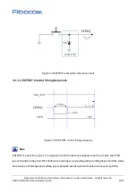
l
The length of route from the module to the SIM card slot should not exceed 100 mm, and too long
route will reduce the signal quality;
l
SIM_CLK and SIM_IO signals are isolated by ground line to avoid mutual interference. If it is difficult
to complete it, at least SIM signal needs to be used for a group of signal protection signal;
l
The filter capacitor and ESD device of SIM card signal line are placed close to the SIM card slot, and
the upper limit of equivalent capacitance of ESD device is 33 pF.
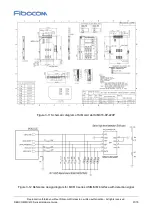
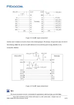
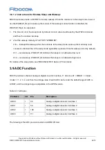
3.6 UART Interface
3.6.1 UART Interface Definition
There are four groups of serial ports in MC610 modules: main serial port UART1, downloading interface
UART2, serial port UART3 and serial port DEBUG. The main features of four serial ports are described
below:
Main serial ports UART1 and UART3 support the baud rate of 2,400 bps, 4,800 bps, 9, 600 bps,14,400
bps,19,200 bps, 28,800 bps, 33,600 bps, 38,400 bps, 57,600 bps, 115,200 bps, 230,400 bps, 460,800
bps, 921,600 bps and 1,000,000 bps. The default baud rate is 115,200 bps, which is used for data
transmission and AT command transmission. But only UART1 can continuously send the AT command to
wake up the module after the module is sleeping, and other serial ports are unavailable.
DEBUG serial port supports the baud rate of 115,200 bps, which is used for FIBOCOM internal
debugging.
Each serial port pin is described as shown in the following table:
Table 3-11 UART1 pins
Pin Name
I/O
Pin
Description
UART1_RX
I
18
Module receiving data
UART1_TX
O
19
Module transmitting data
UART1_RTS
O
20
DTE request to transmit data
UART1_CTS
I
21
Module clearing transmitting


