
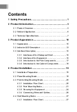


2 Product Introduction
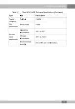
Table 2.1
The AN5121-4GP Technical Specifications (Continued)
Type
Item
Description
MAC address
The capacity of the system MAC address
table is 1K.
Layer 2 line rate
forwarding
All ports support line rate forwarding.
QoS
Supports eight priority queues at most.
Supports the SP, WRR, and SP + WRR
scheduling modes. The SP scheduling
mode is used by default.
Network
side
interface
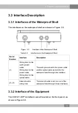
GPON interface
One GPON interface is available, which
meets the ITU-T G.984 standard.
User side
interface
GE interface
Four GE interfaces are available, whose
type is RJ-45. They support 10 / 100 /
1000 Mbit/s full-duplex / half-duplex
adaptation.
Network cables are category-5
waterproof cables.
Supports the PoE function, based on the
IEEE 802.3AF / AT standard. For the
PoE, the maximum output power of the
integrated equipment is 120 (4×30) W,
and the maximum output power of a
single interface is 30 W.
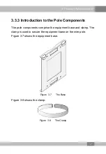
Mechanical
parameters
Waterproof shell
size
80mm × 280mm × 340mm (height x
width x depth).
Equipment size
45 mm × 240 mm × 150 mm (H × W × D)
Weight
<1.5kg
Power
supply
parameters
AC
AC 220 V
8
Содержание AN5121-4GP
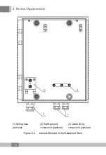
Страница 36: ...4 Product Installation 1 Waterproof connector Figure 4 11 Connecting the Power Cable 32...
Страница 59: ......


