5.2 c
ontrols
,
IndIcators
and
saFety
devIces
easy aIr 2
control
panel
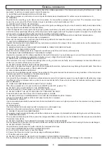
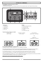
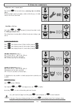
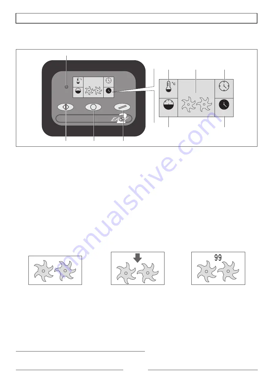
The control panel is made up of a set of buttons required for the main operational and control functions of the compressor.
Control panel
Display
1 - START button
5 - Air-end delivery temperature
2 - STOP button
6 - Compressor state
3 - RESET button
7 - Working hours (total)
4 - Alarm Led
8 - Pressure
9 - Working hours (duty)
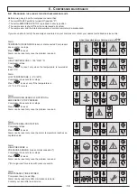
Compressor state (6) - Meaning of simbols
Compressor ON
(rotors moving)
Compressor is charging
(rotors moving)
Idle running time
(rotors countdown)
OR
Restart time
(rotors fl countdown)
Air-end delivery temperature (5) - Possible alarms
The display shows the compressor temperature in °C or °F, it depends on the setting.
The high temperature alarm is 105°C (221 °F) and to reset the alarm the temperature has to decrease under 95 °C (203 °F).
In case of high temperature alarm, the compressor stops (regardless its status) and is not possible to start it again.
The LOW temperature alarm is -5 °C (23°F), and to reset the alarm the temperature has to be above 10°C (50°F).
In case of low temperature alarm, the compressor stops (regardless its status) and is not possibile to start it again.
If the air-end temperature drops below – 40°C (- 40 °F) it means that the temperature sensor is short circuit; in this case the compres-
sor stops immediately regardless of its status and it’s not possible to start it again.
Check page 23, in order to recognize alarms signal and find a solution.
81
50
8.2
55
81
55
8.2
50
1
2
3
4
8
9
5
7
6
13
5. u
sIng
tHe
compressor
Содержание New Silver Series
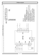
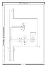
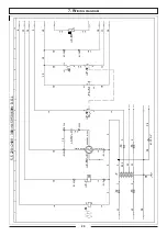
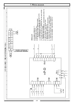
Страница 20: ...7 Wiring diagram 20 7 Wiring diagram ...
Страница 21: ... 21 7 Wiring diagram ...
Страница 22: ... 22 7 Wiring diagram ...
Страница 23: ... 23 7 Wiring diagram ...
Страница 24: ... 24 7 Wiring diagram ...
Страница 25: ... 25 7 Wiring diagram ...
Страница 26: ... 26 7 Wiring diagram ...
Страница 27: ... 27 7 Wiring diagram ...
Страница 28: ... 28 7 Wiring diagram ...
Страница 29: ... 29 7 Wiring diagram ...
Страница 30: ... 30 7 Wiring diagram ...
Страница 31: ... 31 7 Wiring diagram ...
Страница 32: ... 32 7 Wiring diagram ...
Страница 33: ... 33 7 Wiring diagram ...
Страница 34: ... 34 7 Wiring diagram ...
Страница 35: ... 35 7 Wiring diagram ...
Страница 36: ... 36 7 Wiring diagram ...
Страница 37: ...37 7 Wiring diagram 7 Wiring diagram ...
Страница 38: ...38 7 Wiring diagram ...
Страница 39: ...39 7 Wiring diagram ...
Страница 40: ...40 7 Wiring diagram ...
Страница 41: ...41 7 Wiring diagram ...
Страница 42: ...42 7 Wiring diagram ...
Страница 43: ...43 7 Wiring diagram ...
Страница 44: ...44 7 Wiring diagram ...
Страница 45: ...45 7 Wiring diagram ...
Страница 46: ...46 7 Wiring diagram ...
Страница 47: ...47 7 Wiring diagram ...
Страница 48: ...48 7 Wiring diagram ...
Страница 49: ...49 7 Wiring diagram ...
Страница 50: ...50 7 Wiring diagram ...
Страница 51: ...51 7 Wiring diagram ...
Страница 52: ...52 7 Wiring diagram ...
Страница 53: ...53 7 Wiring diagram ...
Страница 54: ...54 7 Wiring diagram ...
Страница 55: ...55 7 Wiring diagram ...
Страница 56: ...56 7 Wiring diagram ...
Страница 58: ...Model Serial No Date Intervention Working hours Signature 9 Maintence Schedule 58 9 Maintence Schedule ...
Страница 59: ...59 9 Maintence Schedule ...
Страница 60: ...Cod 1127340124_02 2017 ...


