background image

Farmer-Helper 25 & 27G 

Revision06/2017

SECTION 2:  OPERATION

Understanding Spreader Operation

Proper and safe operation of the F a r m e r  H e l p e r  27G Spreader requires: (1) being familiar  with the

spreader's
operating components and (2) heeding all safety  precautions as stated in this manual.

The Spreader Operating Components

By definition, the left and right sides of the spreader are determined while sitting on the tractor seat.

The following operating components are included with all Model

 21+131+ 

spreaders:

The left hand sp re ad e r lever 

engages thefloor apron chain which moves the manure to the

rear o f  the spreader and into the beater.

The right  hand sp read er lever 

engages the chain that drives the beater and spreads the

manure.

The following are optional operating components included with some Model 

21+131+

 spreaders (depending on

the specific model configuration ordered):

The jack stand dolly wheel option  allows easy movement of the spreader around the stable

or bam; also adjusts the height of the spreader to facilitate hook-up to the spreader towing vehicle.

The end gate helps to contain loads between spreading and also shields the operator during
spreading.

Connecting the Spreader to the Towing Vehicle

For operation in the field, the F a r m e r  H e l p e r  M odel 

27G

 spreaders can be towed by a num ber of vehicles--

garden tractor, A TV , or utility vehicle. Please adhere to the following procedure for connecting the spreader to
your towing vehicle.

  Attaching the spreader to the towing vehicle as instructed is necessary  for safe

and proper operation of the equipment.

1. 

Back the towing vehicle within a few inches o f the spreader hitch.

2. 

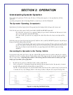
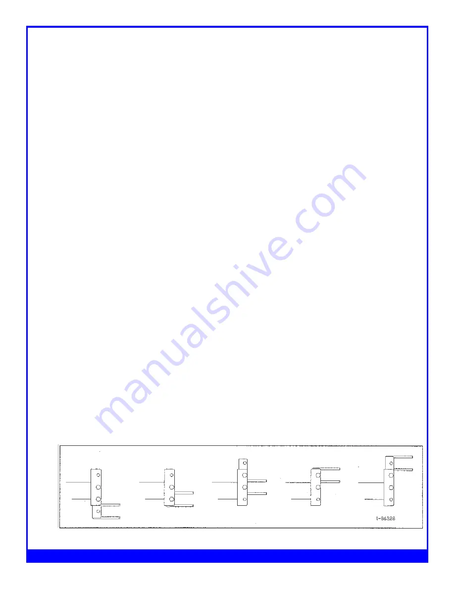
Refer to Figure 2A. Determine the spreader hitch position required to allow  the spreader  to remain
parallel to the ground with relation to the  towing vehicle.
N O TE: As shown in Figure 2A, the adjustable hitch on the front of the spreader may be positioned in
A number of ways, by sliding up/down or inverting, to achieve a higher or lower positioning of the

Figure 2A - Adjusting the Hitch Position

Содержание FH-25G

Страница 1: ...ent Since 1995 www Betstco com Toll Free 877 876 7895 E mail sales betstco com 83371 Melton Rd Creswell OR 97426 Ground Pull Manure Spreaders FH 25 27G Save This Manual for Future Reference OPERATION...

Страница 2: ...ECTION 3 MAINTENANCE ADJUSTMENT 10 Guidelines for Regular Maintenance 10 Procedures for Spreader Adjustment 15 Adjusting the Rear Pawl 15 Re installing the Beater Drive Chain 16 APPENDIX A PARTS REFER...

Страница 3: ...t safety informationfound in this section before beginning any procedures doing so ensures your safety and the optimal performance of your Farmer Helper Spreader For Your Safety For your safety F ar m...

Страница 4: ...ever wear loose clothing when operating the spreader as it may become caught in the moving parts of the machine WA RN IN G Never allow children or anyone else to ride on the spreader AT TENT ION For p...

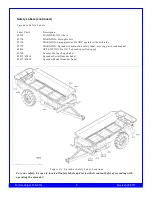
Страница 5: ...RNING Spreader combination safety label moving parts read manual 42814 ATTENTION Do NOT exceed specified speed 42700 Farmer Helper Logo Label 42815 42816 Spreader Serial Number Label 42817 42818 Sprea...

Страница 6: ...Farmer Helper 25 27G 6 Revision06 2017...

Страница 7: ...easy movement of the spreader around the stable or bam also adjusts the height of the spreader to facilitate hook up to the spreader towing vehicle The end gate helps to contain loads between spreadin...

Страница 8: ...age to the spreader or other vehicle as well as injury to the operator may occur if A properly sized hitch pin is not installed as recommended Note that the installation of the safety clip to hold the...

Страница 9: ...the beater 4 Engage the left lever to start the action of the apron floor chain moving the material towards the rear of the spreader 5 Begin moving forward and ensure that you are reaching the optima...

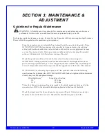
Страница 10: ...n it will accelerate rusting of the steel Check the spreader each time it is used for loose bent broken or missing parts ATTEN TION During operation listen for abnormal sounds which might indicate loo...

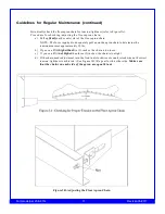
Страница 11: ...adequately pul1up on the apron chain to determine the tension measures approximately 30 lbs b If you can lift it higherthanfive 5 inches the chain istoo loose c If you can lift it not higherthan thre...

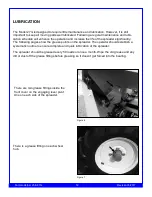
Страница 12: ...y The following pages show the grease points on the spreader The operator should establish a systematic routine to ensure complete and quick lubrication of the spreader The spreader should be greased...

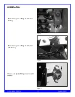
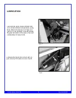
Страница 13: ...27G 13 Revision06 2017 LUBRICATION There is one grease fitting on each axle bearing Figure 8 There is one grease fitting on each rear web bearing Figure 9 There is one grease fitting on each beater b...

Страница 14: ...imilar lubricant at least twice yearly More often if the manure is of high acid nature or if the spreader is stored outside Regular lubrication of the apron chain will substantially increase its life...

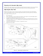
Страница 15: ...d turning the beater by hand you will be able to observe the brake pawl engagement in the sprocket teeth 1 Refer to Figure 3C 2 Remove the shield covering the brake pawl assembly by removing the two 2...

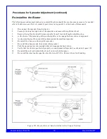
Страница 16: ...the front o fthe spreader pull up on the right lever to engage the beater drive components 5 As shown in Figure 3D re install the chain around the small rear sprocket 6 Re install the chain over the...

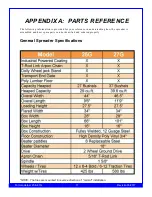
Страница 17: ...The following information is provided for your reference in understanding how the spreader is assembled and how spare parts can be identified and ordered properly General Spreader Specifications NOTE...

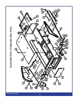
Страница 18: ...Exploded View of 25G Manure Spreader Farmer Helper 25G 18...

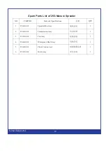
Страница 19: ...PART NO Name Specifications QTY 1 25G 10 001 Spreader Box Assy 1 2 25G 20 001 Transmission Assy 1 3 25G 30 001 Tire Assy 1 4 25G 40 001 Widespread Shaft Assy 1 5 25G 50 001 Chain Tension Assy 1 6 25G...

Страница 20: ...Exploded View of Spreader Box Farmer Helper 25G 20...

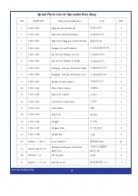
Страница 21: ...ng Linkage Weldment Right 1 8 25G 10 018 Engaging Linkage Weldment Left 1 9 25G 10 019 Handle Grip Weldment 2 10 25G 10 101 Drive Chain Shield 2 1 11 25G 10 102 Push Arm Control 1 12 25G 10 103 Lifter...

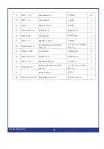
Страница 22: ...4 27 GB96 2 6 Big Plain Washer 6 6 4 28 GB801 M10 25 Round Head Square Neck Bolt M10 25 M10 25 4 29 GB889 1 M8 Lock Nut M8 M8 10 30 GB5783 M10 30 Bolt M10 30 M10 30 9 31 GB96 2 10 Big Plain Washer 10...

Страница 23: ...Exploded View of Transmission Assy Farmer Helper 25G 23...

Страница 24: ...ent 2 1 7 25G 20 017 Front Web Idler Weldment 2 8 25G 20 018 Web Slat Weldment 10 9 300053 Shaft Collar 1 3 10 25G 20 102 Spacer 1 1 11 25G 20 103 Web Sprocket 4 12 25G 20 104 Web Shaft 1 13 25G 20 10...

Страница 25: ...4 32 Cotter Pin 4 32 4 32 2 27 GB6170 M12 Nut M12 M12 1 28 GB97 1 12 Plain Washer 12 12 1 29 GB794 M12 85 Round Head Square Neck Bolt M12 85 M12 85 1 30 GB801 M8 20 Round Head Square Neck Bolt M8 20 M...

Страница 26: ...Exploded View of Tire Assy Farmer Helper 25G 26...

Страница 27: ...cket 1 11 25G 30 108 Spacer 2 2 12 25G 30 109 Hub Dawg Spring Right 1 13 SF 2 40x35x30 Hub Bushing 40x35x30 40x35x30 4 14 GB7810 UCP207 Axle Bearing UCP207 UCP207 2 15 GB889 1 M16 Lock Nut M16 M16 4 1...

Страница 28: ...Exploded View of Widespread Shaft Assy Farmer Helper 25G 28...

Страница 29: ...G 40 103 Shaft Collar 2 2 7 25G 40 104 Widespread Sprocket 1 8 GB7810 UCFLU205 Flange Bearing UCFLU205 UCFLU205 2 9 GB889 1 M8 Lock Nut M8 M8 20 10 GB801 M8 20 Round Head Square Neck Bolt M8 20 M8 20...

Страница 30: ...Exploded View of Chain Tension Assy Farmer Helper 25G 30...

Страница 31: ...Sprocket 1 8 25G 50 105 Shaft Idler Sprocket 1 9 25G 50 106 Bolt Idler Sprocket 1 10 25G 50 107 Guide Bracket 1 11 25G 50 108 Lifter Arm Chain Shield 1 1 12 GB889 1 M8 Lock Nut M8 M8 8 13 GB801 M8 20...

Страница 32: ...Exploded View of Hitch Assy Farmer Helper 25G 32...

Страница 33: ...60 012 Adjustable Hitch Weldment 1 3 25G 60 013 Dolly Jack Bracket Weldment 1 4 Dolly Wheel Jack Assembly 1 5 GB889 1 M12 Lock Nut M12 M12 2 6 GB5782 M12 80 Bolt M12 80 M12 80 2 7 GB97 1 10 Plain Wash...

Страница 34: ...ion06 2017 Parts Request Form Fax to 541 895 2756 or E mail cservice betstproducts com Name Address City State Zip Phone E mail Model Number Serial Number Purchased From Purchase Date ItemNo Descripti...

Страница 35: ...Y EXPRESSLY DISCLAIMS ALL LIABILITY FOR PRODUCT DEFECT OR FAILURE CLAIMS THAT ARE DUE TO NORMAL WEAR PRODUCT MISUSE ABUSE PRODUCT MODIFICATION IMPROPER PRODUCT SELECTION NON COMPLIANCE WITH ANY CODES...

Страница 36: ...ited Warranty is void if any attempt to repair or replace defective parts has been made by unauthorized personnel I acknowledge receipt of my Operators Manual and have read the Safe Operation Section...

Страница 37: ...explained all the above to me I understand this extended warranty does not cover any labor I have filed my Original Warranty Registration and fully understand my requirements I understand that I alone...

Отзывы: