MR25664
9
INSTALLATION & SET-UP
WARNING! READ MANUAL PRIOR TO INSTALLATION
Improper installation, operation, or maintenance of this equipment could result in
serious injury or death. Operators and maintenance personnel should read this
manual, as well as all manuals related to this equipment and the prime mover
thoroughly before beginning installation, operation, or maintenance. FOLLOW ALL
SAFETY INSTRUCTIONS IN THIS MANUAL AND THE PRIME MOVER'S
MANUAL(S).
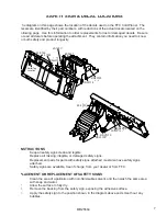
1.
Place this product on a firm, level surface that is large enough to safely accommodate this
product, your prime mover and all workers involved in the mounting process.
2.
Refer to the operator’s manual(s) for your prime mover, loader, and quick-attach and follow the
mounting instructions contained therein.
3.
Carefully raise the loader and cycle the tilt cylinders to check clearances and to verify that all
mounting procedures have been successfully completed.
NOTICE!
Lubricate all grease fittings before connecting this product to your prime
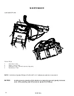
mover's hydraulic system. Refer to COLD PLANER MAINTENANCE page and
follow the instructions.
ELECTRIC HARNESS AND ACTUATOR INSTALLATION
MATERIALS NEEDED: Nylon cable ties.
1.
Attach the control box to a location convenient for the operator to control the planer without
hindering operation of the prime mover. Use the magnet on the back of the control box to
secure the control box with the toggle switches on top.
CAUTION!
Failure to obey the following procedures may result in personal injury.
To avoid electric shock during the wiring harness installation, remove the
ground cable from the battery of your prime mover.
2.
Remove the ground cable from the negative (-) post of your prime mover’s battery.
3.
Remove the nut from the POSITIVE (+) cable clamp on the battery and slide the RED wire
ring terminal from the 9’ wiring harness cable over the positive (+) cable clamp bolt. Secure the
ring terminal with the nut.
4.
Remove the nut from the NEGATIVE (-) cable clamp on the ground cable and slide the BLACK
wire ring terminal from the 6’ wiring harness cable over the negative (-) cable clamp bolt.
5.
Reinstall the ground cable on the negative (-) post of the battery and secure the ring terminal
and the ground cable with the nut removed in the previous step.
6.
Secure the 9’ wiring harness cable from the battery to the control box with your nylon cable ties.
7.
Feed the 16’ wiring harness cable:
a) back to the left-rear area of your prime mover,
b) past the loader arm’s rear hinge point by following the hydraulic hoses where possible, and
c) down the loader arm following the hydraulic lines.
8.
Use your nylon cable ties to secure the 16’ cable’s female connector to the hydraulic lines next
to the auxiliary hydraulic quick couplers.
9.
Straighten the 16’ cable and use your nylon cable ties to secure the cable to the hydraulic lines
back to the loader arm hinge point.
10.
Allow sufficient slack in the cable at the hinge point to provide for a full range of motion of the
loader arms. Use your nylon cable ties to secure the cable to the loader frame below the hinge
point and back to the control box.
11.
Connect the male connector on the actuator cable to the female connector on the loader arm.
Содержание LAF5416
Страница 2: ...NOTES...
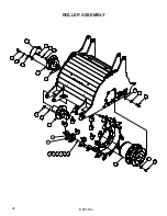
Страница 26: ...MR25664 24 ROLLER ASSEMBLY 14 12 16 3 14 16 12 1 10 19 17 2 18 13 15 17 19 11 4 5 6 7 8 9 20 21...
Страница 37: ...MR25664 35...
Страница 39: ......


