background image


MR25664

36

Limited Warranty

Except for the Excluded Products as described below, all new products are warranted to be free from defects 
in material and/or workmanship during the Warranty Period, in accordance with and subject to the terms and 
conditions of this Limited Warranty.  

1. 

Excluded Products.  The following products are excluded from this Limited Warranty:

(a)  Any cable, part that engages with the ground (i.e. sprockets), digging chain, bearing, teeth, tamping 

and/or demolition head, blade cutting edge, pilot bit, auger teeth and broom brush that either constitutes or is part 
of a product.

(b)  Any product, merchandise or component that, in the opinion of Paladin Light Construction

1

, has been 

(i) misused; (ii) modifi ed in any unauthorized manner; (iii) altered; (iv) damaged; (v) involved in an accident; or (vi) 

repaired using parts not obtained through Paladin Light Construction.


2. 

Warranty Period.  The Limited Warranty is provided only to those defects that occur during the Warranty 

Period, which is the period that begins on the 

fi rst to occur

 of: (i) the date of initial purchase by an end-user, (ii) the 

date the product is fi rst leased or rented, or (iii) the date that is six (6) months after the date of shipment by Paladin 

Light Construction as evidenced by the invoiced shipment date (the “Commencement Date”) and ends on the date 
that is twelve (12) months after the Commencement Date.

3. 

Terms and Conditions of Limited Warranty.  The following terms and conditions apply to the Limited Warranty 

hereby provided:

 (a) 

Option to Repair or Replace. Paladin Light Construction shall have the option to repair or replace 

the product.

(b) 

Timely Repair and Notice.  In order to obtain the Limited Warranty, (i) the product must be repaired 

within thirty (30) days from the date of failure, and (ii) a claim under the warranty must be submitted to Paladin Light 
Construction in writing within thirty (30) days from the date of repair. 

 (c) 

Return of Defective Part or Product.  If requested by Paladin Light Construction, the alleged 

defective part or product shall be shipped to Paladin Light Construction at its manufacturing facility or other location 

specifi ed by Paladin Light Construction, with freight PRE-PAID by the claimant, to allow Paladin Light Construction 

to inspect the part or product. 

Claims that fail to comply with any of the above terms and conditions shall be denied. 

LIMITATIONS AND EXCLUSIONS

.

THIS LIMITED WARRANTY IS IN LIEU OF ALL OTHER WARRANTIES, EXPRESS OR IMPLIED, INCLUDING 
WITHOUT LIMITATION THE WARRANTIES OF MERCHANTABILITY, FITNESS FOR A PARTICULAR PURPOSE 
AND ANY WARRANTY BASED ON A COURSE OF DEALING OR USAGE OF TRADE.

IN NO EVENT SHALL PALADIN LIGHT CONSTRUCTION BE LIABLE FOR CONSEQUENTIAL OR SPECIAL 
DAMAGES.

IN NO EVENT SHALL PALADIN LIGHT CONSTRUCTION BE LIABLE FOR ANY LOSS OR CLAIM IN AN 
AMOUNT IN EXCESS OF THE PURCHASE PRICE, OR, AT THE OPTION OF PALADIN LIGHT CONSTRUCTION, 
THE REPAIR OR REPLACEMENT, OF THE PARTICULAR PRODUCT ON WHICH ANY CLAIM OF LOSS OR 
DAMAGE IS BASED.  THIS LIMITATION OF LIABILITY APPLIES IRRESPECTIVE OF WHETHER THE CLAIM 
IS BASED ON BREACH OF CONTRACT, BREACH OF WARRANTY, NEGLIGENCE OR OTHER CAUSE AND 
WHETHER THE ALLEGED DEFECT IS DISCOVERABLE OR LATENT.  

1

Attachment Technologies Inc., a subsidiary of Paladin Brands Holding, Inc. (PBHI) is referred to herein as Paladin Light 

Construction.

February 10, 2010

Содержание LAF5416

Страница 1: ...eeb Rd Dexter MI 48130 United States of America Copyright OPERATOR S AND PARTS MANUAL HIGH FLOW COLD PLANER SERIAL NUMBER ___________________ MODEL NUMBER ___________________ Manual Number MR25664 Mod...

Страница 2: ...NOTES...

Страница 3: ...Y SIGNS DECALS 7 8 INSTALLATION SET UP 9 11 OPERATION 12 MAINTENANCE 13 17 PARTS 18 33 3 LINE ASSEMBLY 18 19 5 LINE ASSEMBLY 20 21 CHASSIS ASSEMBLY 22 23 ROLLER ASSEMBLY 24 25 SIDE SHIFT PIVOT ASSEMBL...

Страница 4: ...only by trained individuals that have read and understand this manual If there is any portion of this manual or function you do not understand contact your local authorized dealer or manufacturer to o...

Страница 5: ...to this equipment and the prime mover thoroughly before beginning installation operation or maintenance FOLLOW ALL SAFETY INSTRUCTIONS IN THIS MANUAL AND THE PRIME MOVER S MANUAL S READ AND UNDERSTAN...

Страница 6: ...c leaks DO NOT USE YOUR HANDS SEE ILLUSTRATION 4 76288 GENERAL SAFETY PRECAUTIONS WARNING PROTECT AGAINST FLYING DEBRIS Always wear proper safety glasses goggles or a face shield when driving pins in...

Страница 7: ...the correct tool for the job at hand Make sure they are in good condition for the task required Wear the protective equipment specified by the tool manufacturer WARNING SAFELY OPERATE EQUIPMENT Do no...

Страница 8: ...LDING OR HEATING Hazardous fumes dust can be generated when paint is heated by welding soldering or using a torch Do all work outside or in a well ventilated area and dispose of paint and solvent prop...

Страница 9: ...issing illegible or damaged safety signs Replacement parts for parts with safety signs attached must also have safety signs attached Safety signs are available free of charge from your dealer or from...

Страница 10: ...G STAND CLEAR PART 50 10017 WARNING READ MANUAL PART 50 0724 WARNING HIGH PRESSURE FLUID PART 50 0721 WARNING CRUSH HAZARD PART RDL3159 CAUTION FLYING DEBRIS PART RDL3179 LIFT POINT PART 41043 WARNING...

Страница 11: ...jury To avoid electric shock during the wiring harness installation remove the ground cable from the battery of your prime mover 2 Remove the ground cable from the negative post of your prime mover s...

Страница 12: ...and return hoses When disconnecting the hoses it is recommended to disconnect the case drain line last 2 Connect the power and return couplers to the high flow auxiliary hydraulic system of your skid...

Страница 13: ...READ AND UNDERSTAND THE SAFETY INSTRUCTIONS BEFORE BEGINNING ANY COLD PLANER SETUP From the operator s position The left switch controls the Planer Tilt The middle switch controls the Planer Sideshift...

Страница 14: ...Slightly lift the front loader wheels to create a downward force on the planer Slowly move forward planing in a straight line NOTE Materials can vary greatly it is recommended that cutting depth be l...

Страница 15: ...tachment must be raised block the machine with blocks or jackstands NOT lift jacks or hoists Always block the rear wheels of the Planer in a manner that stabilizes the chassis Always wear protective e...

Страница 16: ...ase or equivalent Grease Fittings 1 Weld Pivot 3 Total 2 Caster 1 each 4 Total 3 Mounting 4 Total 2 hidden behind mounting plate 4 Depth Guide 2 Total NOTICE Avoid excessive greasing Dirt collects on...

Страница 17: ...er 50 hours of operation Subsequent oil change should be every 1000 hours of operation or annually whichever comes first Planetary gearbox is to be half full of oil when the unit is mounted level and...

Страница 18: ...MR25664 16 MAINTENANCE MAINTENANCE RECORD Use this log to record maintenance performed on the attachment Date Maintenance Procedure Performed Performed by Comments...

Страница 19: ...ng parts to come to a stop and relieve all pressure in the hydraulic lines CAUTION Picks become hot during operation Wait for picks to cool before replacing Do not hammer on carbide point when replaci...

Страница 20: ...25 39 36 24 45 27 21 19 43 18 32 33 49 40 26 53 52 34 45 37 44 42 13 6 23 16 to 24 inch unit shown Item Part Qty Description 1 03 10013 1 Hose 5 x 56 8FF45 12FF 100R2 2 03 10014 1 Hose 75 x 52 12FF 1...

Страница 21: ...26 105840 1 Washer Fender 27 13 50811 1 Plate Manifold Guard 28 3338 1 Fitting 6FB 8MB 29 LAF4203 1 Fitting 6MB 8FB 30 LAF4537 1 O Ring 155 094 x 4 x 4 19 31 LAF4707 1 Check Valve Fitting Style 5K 12M...

Страница 22: ...ASSEMBLY 16 to 24 inch unit shown Item Part Qty Description 1 03 10016 1 Manifold 5 Line 2 03 10027 2 Hose 38 x 87 6FF 10MB 100R2 3 03 10029 1 Hose 25 x 42 5 4FF 4FF45 100R2 16 24 in 4 03 10030 1 Hose...

Страница 23: ...itting Style 5K 12MF 12MF 31 LAF4708 1 Tube Assembly Motor Recirculation 32 LAF4712 1 Hose 75 x 97 12FF90 12MB 5K 33 LAF4713 1 Hose 75 x 94 12FF45 12MB 34 LAF4714 1 Hose 38 x 94 8FF45 8MB 35 LAF9325 1...

Страница 24: ...MR25664 22 CHASSIS ASSEMBLY 13 1 1 3 26 2 23 22 24 14 15 25 4 25 20 19 24 22 23 12 3 25 25 16 17 25 25 5 18 26 21 6 7 8 9 10 11...

Страница 25: ...36 inch 12 LAF9342 1 Weld Skid Depth Planetary Side 13 LAF9343 1 Weld Skid Depth DeadShaft Side 14 LAF9344 1 Weld Planetary Support 15 LAF9347 2 Pin Dual Snap Ring 1 7 907 16 LAF9350 2 Weld Depth Indi...

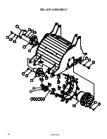
Страница 26: ...MR25664 24 ROLLER ASSEMBLY 14 12 16 3 14 16 12 1 10 19 17 2 18 13 15 17 19 11 4 5 6 7 8 9 20 21...

Страница 27: ...ary 19 62 1 12 P851108 4 Washer Lock 1 2 13 P851110 6 Washer Lock 5 8 14 RHW1407 4 Screw HHC Gr5 1 2 x 2 15 RHW1603 6 Screw HHC Gr5 5 8 11 x 1 3 4 16 RHW5432 4 Washer Flat Gr5 1 2 17 RHW5532 13 Washer...

Страница 28: ...MR25664 26 SIDE SHIFT PIVOT ASSEMBLY 2 22 25 17 18 21 4 23 27 3 27 24 19 5 20 11 6 7 8 9 10 12 13 14 15 16 1 26 1...

Страница 29: ...ft 16 inch 12 LAF9378 1 Weld Side Shift 18 inch 13 LAF9379 1 Weld Side Shift 20 inch 14 LAF9380 1 Weld Side Shift 24 inch 15 LAF9381 1 Weld Side Shift 30 inch 16 LAF9382 1 Weld Side Shift 36ft 17 P100...

Страница 30: ...ABELS DECALS 15 15 16 11 12 10 7 18 18 15 11 8 13 6 2 4 14 9 7 17 5 15 15 11 12 7 10 3 19 1 5 15 15 16 11 12 10 7 18 18 15 11 4 14 9 7 17 1 12 7 19 1 12 18 18 15 11 8 13 6 2 4 14 9 7 17 5 15 15 11 12...

Страница 31: ...rd 7 50 0737 2 Label Warning Pinch Point Hazard 8 50 0856 1 Label Serial Number FFC 9 50 10017 1 Label Warning Avoid Serious Injury 10 LAF8231 1 Non Skid Tape 11 RDL3100 2 Label Warning Flying Objects...

Страница 32: ...0392 2 Rod 2 X 47 25 2 13 50445 2 Tube Spacer 2 75 x 2 063 x 6 36 inch only 3 LAF9319 0022 1 Weld Plate Universal 12 to 24 inches 13 50434 1 Weld Plate Universal 30 to 36 inches 5 LAF9326 1 Tool Pick...

Страница 33: ...Drain Item Part Qty Description 1 LAF4455 1 QD Case Drain 2 P272670 1 QD 8FF Female 12FB 3 P272671 1 QD 8FF Male 12FB Item Part Qty Description 1 LAF4461 1 QD Case Drain 2 LAF4745 1 QD 63 ISO Male 12F...

Страница 34: ...MR25664 32 QUICK DISCONNECT KIT 5 LINE Male Case Drain Item Part Qty Description 1 LAF4461 1 QD Case Drain 2 LAF4747 1 QD 12FF Male 12FB ISO 3 LAF4748 1 QD 12FF Female 12FB ISO 11 5441 12 1 2 3...

Страница 35: ...ption 1 03 10143 1 QD 6FF Female 6FB 2 03 10144 1 QD 6FF Male 6FB 3 03 4880 2 Fitting 8MB 10FB 4 LAF4203 2 Fitting 6MB 8FB Item Part Qty Description 1 03 4618 2 Fitting 12FB 12MB 2 P272670 1 QD 8FF Fe...

Страница 36: ...tor s manual s for your prime mover loader and quick attach for ballasting needs COLD PLANER SPECIFICATIONS Model Number Cutting Width Cutting Depth Tilt Sideshift Overall Width Overall Height Overall...

Страница 37: ...MR25664 35...

Страница 38: ...the option to repair or replace the product b Timely Repair and Notice In order to obtain the Limited Warranty i the product must be repaired within thirty 30 days from the date of failure and ii a cl...

Страница 39: ......

Отзывы: