background image

2/19/09

MR15554

9

BOLT TORQUE

BOLT TORQUE SPECIFICATIONS

GENERAL TORQUE SPECIFICATION TABLES

8VHWKHIROORZLQJFKDUWVZKHQGHWHUPLQLQJEROWWRUTXHVSHFL¿FDWLRQVZKHQVSHFLDOWRUTXHVDUHQRW

given.  Always use grade 5 or better when replacing bolts. 

SAE BOLT TORQUE SPECIFICATIONS

NOTE: The following torque values are for use with extreme pressure lubricants, plating or hard washer 
applications Increase torque 15% when using hardware that is unplated and either dry or lubricated with 
engine oil. 

Bolt Size

SAE GRADE 5 TORQUE

SAE GRADE 8 TORQUE

Pounds Feet

Newton-Meters

Pounds Feet

Newton-Meters

%ROWKHDGLGHQWL¿FDWLRQPDUNVDVSHUJUDGH

NOTE: Manufacturing Marks Will Vary

Inches

Millimeters

UNC

UNF

UNC

UNF

UNC

UNF

UNC

UNF

1/4

6.35

8

9

11

12

10

13

14

18

5/16

7.94

14

19

19

23

20

25

27

34

3/8

9.53

30

36

41

49

38

46

52

62

7/16

11.11

46

54

62

73

60

71

81

96

1/2

12.70

68

82

92

111

94

112

127

152

9/16

14.29

94

112

127

152

136

163

184

221

5/8

15.88

128

153

174

207

187

224

254

304

3/4

19.05

230

275

312

373

323

395

438

536

7/8

22.23

340

408

461

553

510

612

691

830

1

25.40

493

592

668

803

765

918

1037

1245

1-1/8

25.58

680

748

922

1014

1088

1224

1475

1660

1-1/4

31.75

952

1054

1291

1429

1547

1700

2097

2305

1-3/8

34.93

1241

1428

1683

1936

2023

2312

2743

3135

1-1/2

38.10

1649

1870

2236

2535

2686

3026

3642

4103

METRIC BOLT TORQUE SPECIFICATIONS

NOTE: The following torque values are for use with metric hard-
ware that is unplated and either dry or lubricated with engine oil.
Reduce torque 15% when using hardware that has extreme 
pressure lubricants, plating or hard washer applications.

Size of Bolt

Grade No.

Pitch (mm)

Pounds Feet

Newton-Meters

Pitch (mm)

Pounds Feet

Newton-Meters

5.6

3.6-5.8

4.9-7.9

-

-

M6

8.8

1.0

5.8-.4

7.9-12.7

-

-

-

10.9

7.2-10

9.8-13.6

-

-

5.6

7.2-14

9.8-19

12-17

16.3-23

M8

8.8

1.25

17-22

23-29.8

1.0

19-27

25.7-36.6

10.9

20-26

27.1-35.2

22-31

29.8-42

5.6

20-25

27.1-33.9

20-29

27.1-39.3

M10

8.8

1.5

34-40

46.1-54.2

1.25

35-47

47.4-63.7

10.9

38-46

51.5-62.3

40-52

54.2-70.5

5.6

28-34

37.9-46.1

31-41

42-55.6

M12

8.8

1.75

51-59

69.1-79.9

1.25

56-68

75.9-92.1

10.9

57-66

77.2-89.4

62-75

84-101.6

5.6

49-56

66.4-75.9

52-64

70.5-86.7

M14

8.8

2.0

81-93

109.8-126

1.5

90-106

122-143.6

10.9

96-109

130.1-147.7

107-124

145-168

5.6

67-77

90.8-104.3

69-83

93.5-112.5

M16

8.8

2.0

116-130

157.2-176.2

1.5

120-138

162.6-187

10.9

129-145

174.8-196.5

140-158

189.7-214.1

5.6

88-100

119.2-136

100-117

136-158.5

M18

8.8

2.0

150-168

203.3-227.6

1.5

177-199

239.8-269.6

10.9

175-194

237.1-262.9

202-231

273.7-313

5.6

108-130

146.3-176.2

132-150

178.9-203.3

M20

8.8

2.5

186-205

252-277.8

1.5

206-242

279.1-327.9

10.9

213-249

288.6-337.4

246-289

333.3-391.6

%ROWKHDGLGHQWL¿FDWLRQPDUNVDVSHUJUDGH

Содержание 13884

Страница 1: ... 503 Gay Street Delhi IA 52223 United States of America SERIAL NUMBER ___________________ Manual Number MR15554 Part Number 13884 13888 MODEL NUMBER ___________________ Rev 2 OPERATOR S AND PARTS MANUAL BOX SCRAPER 2 19 09 13888 Shown ...

Страница 2: ......

Страница 3: ... 2 SERIAL NUMBER 2 OWNER AND OPERATOR SAFETY INFORMATION SAFETY STATEMENTS 3 SAFETY PRECAUTIONS 4 5 SAFETY SIGNS 6 7 SPECIFICATIONS 8 9 MOUNTING 10 HYDRAULIC CONNECTION 11 SETUP 12 OPERATION 13 MAINTENANCE 14 15 SERVICE 16 17 PARTS ILLUSTRATION 18 PARTS LIST 19 WARRANTY i ...

Страница 4: ...s to assist in assembling mounting operating and maintaining your Box Scraper Read this manual carefully to obtain valuable information and instructions that will help you achieve years of safe and dependable service The illustrations and data used in this manual were current at the time of printing but due to possible engineering and or production changes this product may vary slightly in detail ...

Страница 5: ...lated to this equipment and the prime mover thoroughly before beginning installation operation or maintenance FOLLOW ALL SAFETY INSTRUCTIONS IN THIS MANUAL AND THE PRIME MOVER S MANUAL S READ AND UNDERSTAND ALL SAFETY STATEMENTS Read all safety decals and safety statements in all manuals prior to operating or working on this equipment Know and obey all OSHA regulations local laws and other profess...

Страница 6: ...WITH HYDRAULIC FLUID PRESSURE Hydraulic fluid under pressure can penetrate the skin and cause serious injury or death Hydraulic leaks under pressure may not be visible Before connecting or disconnecting hydraulic hoses read your prime movers operator s manual for detailed instructions on connecting and disconnecting hydraulic hoses or fittings Keep unprotected body parts such as face eyes and arms...

Страница 7: ... specified by the tool manufacturer WARNING SAFELY OPERATE EQUIPMENT Do not operate equipment until you are completely trained by a qualified operator in how to use the controls know its capabilities dimensions and all safety requirements See your machine s manual for these instructions Keep all step plates grab bars pedals and controls free of dirt grease debris and oil Never allow anyone to be a...

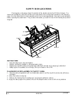
Страница 8: ...S Keep all safety signs clean and legible Replace all missing illegible or damaged safety signs Replacement parts for parts with safety signs attached must also have safety signs attached Safety signs are available free of charge from your dealer or from FFC PLACEMENT OR REPLACEMENT OF SAFETY SIGNS 1 Clean the area of application with non flammable solvent and then wash the same area with soap and...

Страница 9: ...2 19 09 MR15554 7 SAFETY SIGNS PART 40150 WARNING READ MANUAL PART 50 0724 WARNING HIGH PRESSURE FLUID PART 50 0737 WARNING PINCH POINT HAZARD PART RDL3155 RED REFLECTIVE TAPE ...

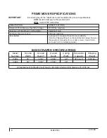
Страница 10: ...aulic Pressure Output 4 000 psi maximum Rear Ballast As required to maintain full prime mover stability Note the Shipping Weight on the specifications page then see the operator s manual s for your prime mover 3 point hitch and quick hitch for ballasting needs BOX SCRAPER SPECIFICATIONS Model Number Overall Width Overall Height Overall Depth Cutting Width Excavation Capacity Shipping Weight 13884 ...

Страница 11: ... 2312 2743 3135 1 1 2 38 10 1649 1870 2236 2535 2686 3026 3642 4103 METRIC BOLT TORQUE SPECIFICATIONS NOTE The following torque values are for use with metric hard ware that is unplated and either dry or lubricated with engine oil Reduce torque 15 when using hardware that has extreme pressure lubricants plating or hard washer applications Size of Bolt Grade No Pitch mm Pounds Feet Newton Meters Pi...

Страница 12: ... PRIME MOVER S MANUAL S 1 Place this product on a firm level surface that is large enough to safely accommodate this product your prime mover and all workers involved in the mounting process 2 Refer to the operator s manual s for your prime mover 3 point hitch and quick hitch and follow the mounting instructions contained therein 3 Carefully raise the 3 point hitch to check clearances and to verif...

Страница 13: ...or your prime mover will describe the exact type of fitting that is needed for your hydraulic coupling system but in no case should any fitting have an allowable operating pressure of less than 4 000 psi Once all the quick coupler fittings are properly installed then the hoses can be coupled to the prime mover s hydraulic valve body or auxiliary hydraulic lines as per the instructions found in you...

Страница 14: ...he operator s manual s for the prime mover and 3 point hitch SCARIFYING Perform steps 1 through 6 above Check to see that the bases of the main frame end plates are leaning forward approximately 15 degrees relative to the level surface If this is not the case adjust the 3 point hitch s top link as described in the operator s manual s for your prime mover and 3 point hitch Leaning this product forw...

Страница 15: ...es IMPORTANT Backing up with any portion of the ripper shanks below the ground surface CAN result in damage to this product and WILL void all FFC warranties Before beginning any work have a qualified individual or firm inspect the entire work area for underground utility lines The operator should carefully inspect the entire area for stumps concrete foundations large rocks posts or any other solid...

Страница 16: ... and bolts are in place and properly tightened Make sure that all other fasteners are in place and are performing their specified function Make sure that all hydraulic fittings are tightened to specifications and that there are no leaks in any fittings or hoses SEE THE HYDRAULIC CONNECTION SECTION Make sure that all safety signs are in place are clean and are legible SEE THE SAFETY SIGN SECTION Re...

Страница 17: ...2 19 09 MR15554 15 MAINTENANCE MAINTENANCE RECORD Use this log to record maintenance performed on the attachment Date Maintenance Procedure Performed Performed by Comments ...

Страница 18: ...pper shank that extends to the front side of the scarifier tube and lift up while pushing down with the other hand on the opposite end of the ripper shank When clear of the ripper shank slot slide the ripper shank to the other slot or completely out to the rear of the scarifier tube whichever is the desired option For ripper shank adjustment or replacement skip to step 11 To replace the shank poin...

Страница 19: ... product is completely stable on the blocking If the blocking appears to be unstable or is even of questionable stability restart your prime mover raise this product off the blocking and move away from the blocking After the blocking has been repositioned in a more stable fashion repeat steps 1 through 5 until a completely stable condition exists 6 TWO WORKERS ARE REQUIRED to remove a cutting edge...

Страница 20: ...15554 18 BOX SCRAPER PARTS ILLUSTRATION 8 3 41 29 3 3 29 34 18 24 1 33 30 27 9 26 32 2 26 7 12 25 42 24 31 12 32 36 23 35 4 29 3 14 28 31 20 23 21 19 37 35 11 5 29 3 11 35 40 43 38 13 31 44 15 16 39 17 15 6 10 22 ...

Страница 21: ...Cylinder 3 Piston x 6 Stroke x 1 75 Shaft 22 1 LAF9401 Split Sleeve 1 25 x 1 x 2 with Ext Grease Groove 23 2 LAF9798 Cylinder Pin 1 x 7 5 24 3 1047 Hex Head Cap Screw 38 x 2 Grade 5 25 1 1116 Hex Head Cap Screw 63 x 2 Grade 5 26 varies 14 26 10150 Plow Bolt 63 x 2 Grade 8 27 10 n a 1528 Flat Washer SAE 63 Grade 5 28 6 1706 Flat Washer SAE 1 Grade 8 Yellow 29 5 RHW5973 Machinery Bushing 2 x 1 x 0 0...

Страница 22: ...ption to repair or replace the product b Timely Repair and Notice In order to obtain the Limited Warranty i the product must be repaired within thirty 30 days from the date of failure and ii a claim under the warranty must be submitted to Paladin Light Construction in writing within thirty 30 days from the date of repair c Return of Defective Part or Product If requested by Paladin Light Construct...

Страница 23: ......

Отзывы: