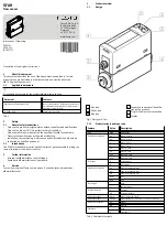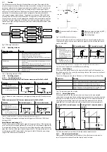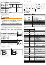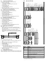
Example for LCD display
Meaning
Main display
Lower display
[16]
[Filt] / [MSEC]
Value of the filter time constant for the measure-
ment signal
[L.Min]
[FLOW Unit]
Display unit for flow rate measurement
[0°C]
[REF] / [Cond]
Reference standard for gas volume
[Air]
[GAS]
Selection of the operating medium
[1->2]
[FLOW] / [Path]
Selection of the flow direction from Port 1 to 2 or
vice versa (only for bidirectionally calibrated
product variant)
[ON]
[Z.Adj]
Offset synchronisation for display, switching and
analogue output
[Unit]
[Sub.d]
Settings of the lower display in RUN mode: selec-
ted unit or switching point of OutA or bar graph
or gas or flow direction
[40]
[Eco] / [SEC]
Economy mode: period after which the display
background lighting is switched off
[PNP]
[bin] / [Out]
Shift of the switching outputs (binary) between
PNP and NPN
[Flow]
[bin] / [Pin4]
Shift of binary switching output or pulse output.
Pin 4 with M8 variant, pin 2 with L1 variant
[bin]
[FLOW] / [Pin2]
Shift of binary switching output or analogue out-
put to pin 2 in M8 variant, pin 3 with L1 variant
[OFF]
[Code]
Activation and determination of the security
code
[OFF]
[MASt]
Activation of the IO-Link® master function for
replication of parameters
Tab. 15
8.2
Switch on sensor (RUN mode)
•
Switch on the operating voltage.
Ä
Current measured value is displayed. The sensor is in the basic status
(RUN mode).
The basic static can be established using the following actions:
–
Press the Edit button for 3 seconds
–
Expiration of a monitoring time (timeout)
8.3
Switchover of measured value indicator
•
Switchover to flow rate measurement: press A pushbutton.
•
Switchover to volume measurement: press B pushbutton.
8.4
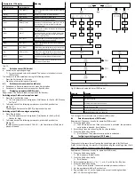
Displaying parameters (SHOW mode)
Requirement: The sensor is ready for operation (RUN mode).
Switching output OutA or volume pulse output
1. Press the A pushbutton twice.
Ä
The first parameter set is displayed. [Fctn] flashes for OutA or [SP] flashes
for “Puls”.
2. To display each of the following parameters, press the A pushbutton
(
è
Fig.10).
The averaged flow rate value [AVER] is displayed at the end.
Switching output OutB or analogue output Anlg
1. Press B pushbutton
Ä
The first parameter set is displayed. [Fctn] flashes for OutB or [Out]
flashes for Anlg.
2. To display each of the following parameters, press the A pushbutton
(
è
Fig.10).
For bidirectional product variant SFAH-...B-..., the flow direction [Path] is dis-
played at the end.
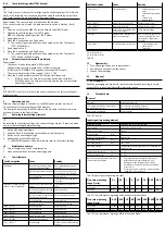
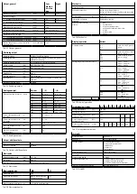
Fig. 10 Measured value indicator (RUN mode)
Legend
Meaning
Edit button
A or B pushbutton
Double-press the A or B pushbutton
1)
Not for flow unit G.Min
2)
Only for bidirectional product variant
3)
Selectable values: 256, 512, 1024 ms
Tab. 16 Legend for measured value indicator (RUN mode)
8.5
Enter the security code (EDIT mode)
Requirement: The sensor is ready for operation (RUN mode).
1. Press the Edit button.
Ä
The EDIT mode is active. If the security code is activated, the parameter
entry option is blocked: [Lock] flashes.
2. Enter the set security code using the A or B pushbutton.
3. Press the Edit button briefly.
Ä
[OutA] flashes. The parameter entry option is unblocked.
8.6
Configuring switching output (EDIT mode)
The process is the same for configuring the switching outputs for [OutA] and
[OutB.] In the following, the process is described using the switching output OutA.
Menu structure
è
8.12 Menu structure (EDIT mode).
Requirement: The sensor is ready for operation (RUN mode).
1. Press the Edit button briefly.
Ä
[Edit] appears. [OutA] flashes.
2. Press the Edit button briefly.
Ä
[Fctn] flashes.
3. Select switching function _I¯ or _I¯I_ or d_I¯I_ with the A or B button.
4. Press the Edit button briefly.
Ä
The set value is saved. The next adjustable parameter is shown.
5. Set the parameter with A or B pushbutton.
6. Repeat steps 4 and 5 until all parameters are set (switching functions
è

