
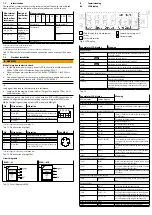

5.2.4
Switchover of standard condition – REF / Cond
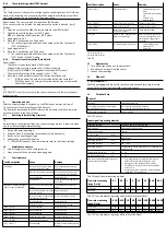
The represented flow rate and volume units can be related to different standard
conditions. It is possible to switch between the following standard conditions. In
the menu navigation on the display, the corresponding standard is determined by
selecting the reference temperature.
REF / Cond
Off
15°C
20°C
Standard
DIN 1343
ISO 2533
ISO 6358
Air pressure (absolute)
[kPa]
101.325
101.325
100
Temperature
[°C]
0
15
20
Humidity
[%]
0
0
65
Status information “Option”
Does not light
up
Lit
Lit
Correction factor, measurement range limit value
1
1.055
1.087
Tab. 9 Standard conditions for flow rate and volume units
Calibration of the SFAH refers back to the physical standard conditions in accord-
ance with DIN 1343.
If a standard other than DIN 1343 is selected, the specified measurement range
(±100%FS) changes in value by the factor specified in
è
Tab. 9 Standard conditions for flow rate and volume units. This change is visu-
alised in the display through [Option].
Changing the reference standard only adjusts the display on the sensor. If neces-
sary, the effect on the nominal measurement range of the respective sensor must
also be considered when evaluating the analogue output.
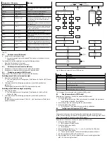
6
Assembly
Any mounting position is possible but can have an influence on measurement pre-
cision (
è
Plate mounting
Fig. 4 Plate mounting
•
Secure the SFAH to the plate by using screws of suitable length.
–
Hole diameter: max 3 mm
–
Tightening torque: 0.5 Nm
Lateral plate mounting
Fig. 5 Lateral plate mounting
1. Mount H-rail mounting on the SFAH. Tightening torque 0.5 Nm.
2. Mount H-rail mounting with washers and M4 screws. Tightening torque
0.5 Nm
Hrail mounting
Fig. 6 H-rail mounting
1. Mount H-rail mounting on the SFAH. Tightening torque 0.5 Nm.
2. Hang H-rail mounting in the H-rail
1
.
3. Press the H-rail mounting in the direction of the arrow until the mounting
slide catches
2
.
Wall mounting
Fig. 7 Wall mounting
1. Screw wall mounting to SFAH. Tightening torque 0.5 Nm.
2. Install wall mounting.
Front panel mounting kit (accessory)
Fig. 8 Front panel mounting kit
–
Permissible front panel thickness: 1 … 3 mm
1. Mount H-rail mounting on the SFAH. Tightening torque 0.5 Nm.
2. Mount accompanying hexagon head screw on the H-rail mounting.
3. Push the panel frame through the cut-out (62 mm x 24 mm ± 0.1 mm).
4. Push the sensor through the panel frame so that all 4 detent hooks engage.
5. Push the clamping element over the hexagon head screw.
6. Attach the sensor with the included knurled nut. Tightening torque 0.3 Nm.
7
Installation
7.1
Pneumatic installation
•
Mount the hoses to connection 1 and connection 2 (marking on the product).
SFAH-…U-…: If the tubing connection is incorrect, the measurement values are
presented with a minus sign and lie outside the specified measurement range.
SFAH-…B-…: The display of the flow direction with the correct sign can be set in
the Edit menu and shown in the sub-display.