background image

SDE3−...

Festo  SDE3−...  0604a  English

47

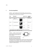
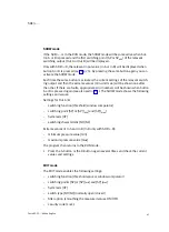
5. In  order  to  accept  the  measured  value  as  the  second  teaching  point  (TP2),  first

press  the  button  selected  under  2.,  then  press  the  EDIT  button  whilst  holding
down  the  switching  output  button.  The  new  switching  point  (SP)  or  the  new
switching  points  (SP

min

  and  SP

max

)  will  then  become  valid.  The  SDE3−...  is  then

in  the  RUN  mode  again.

Minimum/maximum  value  (extreme  values)

The  minimum  and  maximum  measured  pressure  value  is  saved  in  the  SDE3−...  . 
The  minimum/maximum  values  will  be  lost  if  the  power  supply  is  switched  off.  The
SDE3−..D  has  two  independently  working  sensor  elements  (A  and  B).  A  minimum
value  and  a  maximum  value  are  saved  for  each  sensor  element.

Display/delete  minimum/maximum  value

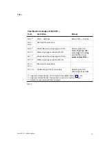
1. By  repeatedly  pressing  the  A−button  (UP)  or  the  B−button  (DOWN),  you  can

display  the  current  settings  for  a  switching  output  (Out  A  or  Out  B)  until  the
display  [min]  flashes.  The  relevant  minimum  value  (smallest  measured  value  of
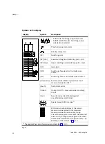
In  A/B)  will  be  shown  (symbols  used  in  display  of  extreme  values  see  Fig.12).

2. In  order  to  delete  the  minimum  value,  press  the  EDIT  button  briefly.  The  mini

mum  value  will  then  be  deleted.

3. Press  the  UP  or  DOWN  button  again.  [max]  flashes.  The  relevant  maximum

value  (largest  measured  value  of  In  A/B)  will  be  shown.

4. In  order  to  delete  the  maximum  value,  press  the  EDIT  button  briefly. 

The  maximum  value  will  then  be  deleted.

5. Press  the  A−button  (UP)  or  the  B−button  (DOWN)  again.

The  SDE3−...  is  then  in  the  RUN  mode  again.

Test  run

S

Carry  out  a  test  run  with  various  pressures  to  ascertain  whether  the  SDE3−...
switches  as  desired.

Содержание SDE3 series

Страница 1: ... de Bedienungs anleitung en Operating instructions Druck Vakuumsensor Pressure vacuum sensor SDE3 704 126 0604a US patent no 6 429 548 ...

Страница 2: ...alifi ziertem Fachpersonal gemäß Bedienungs anleitung Warnung Warning Caution Hinweis Please note Umwelt Antipollution Zubehör Accessories Fitting and commissioning to be carried out by qualified personnel only in accordance with the operating instructions Deutsch 3 English 31 ...

Страница 3: ...dung 8 4 Voraussetzungen für den Produkteinsatz 9 5 Einbau 10 Mechanisch 10 Pneumatisch 11 Elektrisch 11 6 Inbetriebnahme 12 Symbolik auf dem Display 13 Inbetriebnahme Vorbereitung 15 Probelauf 20 7 Bedienung und Betrieb 21 8 Wartung und Pflege 21 9 Ausbau 22 10 Zubehör 22 11 Störungsbeseitigung 23 12 Technische Daten 25 13 Menüstruktur 27 Symbolik zur Darstellung der Menüstruktur 27 ...

Страница 4: ...für elektrischen Anschluss 4 SDE3 für Fronttafeleinbau 5 Spannplatte für Fronttafeleinbau 6 Befestigungsschieber rückseitig 7 SDE3 D Druckluft oder Vakuum anschlüsse zu In A und In B 8 SDE3 S Druckluft oder Vakuum anschluss zu In A 9 SDE3 Z Druckluft oder Vakuum anschlüsse p1 und p2 zu In A aJ Schildträger aA DOWN Taste B Taste aB UP Taste A Taste aC EDIT Knopf aD Display Bild 1 ...

Страница 5: ...nch of mercury W Werte in inch of water Montage und Anschluss HQ4 Hutschienenbefestigung QS4 Anschluss WQ4 Hutschienenbefestigung mit Wandhalter QS4 Anschluss FQ4 Fronttafeleinbau QS4 Anschluss Elektrische Ausgänge 2P 2 PNP Ausgänge 2N 2 NPN Ausgänge Elektrischer Anschluss M8 Stecker M8 K Kabel 2 5 m mit Aderendhülsen Anschlusskabel Zubehör G Steckdosenkabel SIM gerade 2 5 m W Steckdosenkabel SIM ...

Страница 6: ...len möchten B Taste DOWN drücken Out B blinkt 3 2 mal EDIT Knopf drücken SP Feld blinkt 4 Den gewünschten Schaltpunkt mit den Tasten UP DOWN einstellen 5 EDIT Knopf 3 s gedrückt halten Der SDE3 ist dann im RUN Modus So teachen Sie einen Schaltpunkt 1 Ersten Messdruck anlegen Zuordnung siehe Abschnitt 3 2 Um den Messwert als Teach Punkt TP1 für Out A zu übernehmen zuerst die A Taste dann zusätzlich...

Страница 7: ...r Sensorelement B 2 Messdruck p1 Bezugsdruck p2 Bild 3 Der SDE3 D bietet zwei unabhängig arbei tende Sensorelemente A B in einem Gerät denen jeweils ein Schaltausgang Out A Out B zugeordnet ist Die Messung der Eingangswerte In A In B an den Druckluftanschlüssen erfolgt mit Hilfe piezoresistiver Sensorelemente mit nachge schalteter elektronischer Auswerteeinheit Das Messergebnis wird nummerisch und...

Страница 8: ...stets eingehalten werden S Vergleichen Sie die Grenzwerte in dieser Bedienungsanleitung mit denen Ihres Ein satzfalls z B Betriebsmedium Drücke Kräfte Momente Temperaturen Massen Geschwindigkeiten Spannungen S Berücksichtigen Sie die Umgebungs bedingungen am Einsatzort S Berücksichtigen Sie die Vorschriften der Berufsgenossenschaft des Technischen Überwachungsvereins des VDE oder ent sprechende na...

Страница 9: ...tte montieren z B 2 x M3 1 1 Den SDE3 in die Hutschiene Befestigungsplatteeinhängen und andrücken bis der Befes tigungsschieber einrastet SDE3 in die Aus sparung 70 x 22 mm der Fronttafel einfüh ren Spannplatte ein hängenundandücken bis der Befestigungs schieber einrastet Schrauben eindrehen 2 3 Durchgangs bohrung 3 4 mm 1 Lochbilder siehe Seite 59 2 Bei Fronttafelstärke 2 mm die Unterlegscheiben ...

Страница 10: ...S Verwenden Sie ausschließlich Stromquellen die eine sichere elektrische Trennung der Betriebsspannung nach IEC DIN EN 60204 1 gewährleisten Berücksichtigen Sie zusätzlich die allgemeinen Anforderungen an PELV Stromkreise gemäß IEC DIN EN 60204 1 Hinweis Lange Signalleitungen reduzieren die Störfestigkeit S Stellen Sie sicher dass die Signalleitungen stets kürzer sind als 30 m S Verkabeln Sie den ...

Страница 11: ...gen Sie das gewünschte Schaltverhalten der Schaltausgänge fest Schaltpunkte SP und Hysterese Hy Bei Einstellung Schwellwert Komparator Bei Einstellung Fenster Komparator Bei EinstellungNO Schließer P 1 0 Hy OUT SP Hy Hy P 1 0 OUT SP min SP max Bei EinstellungNC Öffner P 1 0 SP Hy OUT P 1 0 OUT SP min SP max Hy Hy Bild 10 ...

Страница 12: ... NC Schaltcharakteristik Öffner normally closed min max Extremwerte Minimaler maximalerEingangs messwert In A B 1 TeachIn TeachIn Modusaktiv Option Option On Off Messwertglättung ein aus Lock Sicherheitscode aktiv Sperrung gegen unbefugte Parametrierung Spezialmenü SPEC ist aktiv 1 RUN Modus Grafische Anzeige des aktuellen Messwerts bezogen auf den maximalen Mess wert des Messbereichs Die linke Se...

Страница 13: ... Eingangswert In B Segment rechts unten und B und min oder max leuchten 1 SHOW Modusaktiv 7 Segmentanzeige zeigt einen Extremwert von In B Markierte Segmente leuchten SHOW Modusaktiv Diagnose 7 Segmentanzeige zeigt Fehlernummer z B Er01 Markierte Segmente leuchten und Option blinkt EDIT Modusaktiv Spezialmenü SPEC ist geöffnet 7 Segmentanzeige zeigt die eingestellte Filteroption Markierte Segmente...

Страница 14: ...eichbar durch 3 s langes Drücken des EDIT Knopfs oder Ablauf einer Überwachungszeit Timeout siehe Abschnitt 13 Menüstruktur S Schalten Sie die Betriebsspannung ein Der SDE3 befindet sich im RUN Modus S Prüfen Sie die Funktionen des SDE3 Hinweis Eine Übersicht zur Menüstruktur finden Sie in Abschnitt 13 RUN Modus Zeigt den Messwert Relativdruck Differenzdruck und den Signalzustand der Schaltausgäng...

Страница 15: ...rden nach erneutem Drücken der Taste A oder B zuerst entsprechende Fehlernummern angezeigt siehe auch Abschnitt 11 Der SHOW Modus zeigt folgende Einstellungen und Werte Einstellungen für Out A B Schaltfunktion Schwellwert Fenster Komparator Schaltpunkt SP oder SP min und SP max Hysterese HY Schaltcharakteristik NO NC Extremwerte von In A und In B In B nur beim SDE3 D Minimaler Druckwert min Maxima...

Страница 16: ...e lässt sich nun Folgendes wählen siehe auch Bild 23 Ausgang dessen Verhalten eingestellt werden soll Spezialmenü SPEC zum Einstellen der Optionen und des Sicherheitscodes Lock 3 Wenn Sie Out B einstellen möchten B Taste DOWN drücken Out B blinkt 4 Zur Bestätigung des gewählten Ausgangs EDIT Knopf drücken Die aktuell eingestellte Schaltfunktion blinkt 5 Gewünschte Schaltfunktion Schwellwert Fenste...

Страница 17: ...estellt ist S EDIT Knopf drücken Out A blinkt 3 UP Taste drücken bis das Menü SPEC Spezial gewählt ist SPEC blinkt 4 Zur Bestätigung EDIT Knopf drücken Option blinkt 5 Mit UP DOWN Taste die gewünschte Filteroption ON OFF wählen ON Glättung der Messwerte In A B ist aktiv Zeitkonstante ca 500 ms OFF Glättung der Messwerte In A B ist inaktiv 6 Zur Bestätigung EDIT Knopf drücken Lock blinkt 7 Gewünsch...

Страница 18: ...age der Teach Punkte Beispiel Bild 14 Zum Teachen der Schaltgrößen 1 Ersten Messdruck anlegen Relativdruck Differenzdruck p1 p2 2 Um den TEACH Modus zu aktivieren und den Messwert als ersten Teach Punkt TP1 zu übernehmen zuerst die Taste für den gewünschten Schaltausgang Out A B drücken dann bei gedrückter Taste den EDIT Knopf drücken 3 Nur bei aktiver Sicherheitssperre Lock blinkt S UP DOWN Taste...

Страница 19: ...ellungen für einen Schaltausgang Out A oder Out B anzeigen bis die Anzeige min blinkt Der entsprechende Minimalwert kleinster Messwert von In A B wird angezeigt Symbolik bei Anzeige von Extremwerten siehe Bild 12 2 Um den Minimalwert zu löschen EDIT Knopf kurz drücken Daraufhin wird der Minimalwert gelöscht 3 Erneut die UP oder DOWN Taste drücken max blinkt Der entsprechende Maximalwert größter Me...

Страница 20: ...das Rücksetzen auf Werkseinstellung gehen die aktuellen Einstellungen verloren Notieren Sie bei Bedarf diese Einstellungen vor dem Rücksetzen Um den SDE3 auf Werkseinstellung zurückzusetzen 1 Schalten Sie die Betriebsspannung aus 2 Drücken Sie gleichzeitig alle drei Einstellelemente UP DOWN Taste und EDIT Knopf und schalten Sie dabei die Betriebsspannung wieder ein 8 Wartung und Pflege S Schalten ...

Страница 21: ...m SDE3 Demontieren Sie den SDE3 wie folgt SDE3 HQ4 und SDE3 WQ4 SDE3 FQ4 Wandmontageoder Hutschienenbefestigung 1 Plattenmontage Fronttafel 1 2 1 Zuerst den SDE3 anheben 1 Dann den SDE3 vorne wegkippen 2 Bild 16 10 Zubehör Bezeichnung Typ Anschlusskabel 4 polig M8 SIM M8 4 D Adapterplatte für Wandmontage 1 SXE3 W 1 Beim SDE3 WQ4 im Lieferumfang enthalten Bild 17 Bild 15 ...

Страница 22: ...spannung Zul Betriebsspannungs bereich einhalten Fehlernummer Er01 blinkt SDE3 defekt SDE3 zu Festo senden Unvollständige Anzeige im Display Display defekt SDE3 zu Festo senden Falsche Druckanzeige Pneumatische Anschlüsse vertauscht nur bei SDE3 D oder SDE3 Z Verschlauchung gemäß Abschnitt Einbau pneumatisch ausführen SDE3 mit unzulässigem Mediumbetrieben SDE3 austauschen und nur mit Druckluft bet...

Страница 23: ...lfe Er01 2 SDE3 defekt SDE3 zu Festo senden Er02 Er08 Reserviert für Erweiterungen Er09 1 Unterschreitung des Messbereichs bei In A Zul Messbereich einhalten nach Über Unterschrei Er10 1 Überschreitung des Messbereichs bei In A nach Über Unterschrei tung zulässiger Maximal S h Er11 1 Unterschreitung des Messbereichs bei In B g g werte SDE3 austauschen Er12 1 Überschreitung des Messbereichs bei In ...

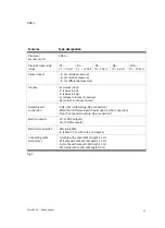
Страница 24: ...h sollte sich kein Kondenswasserim Drucksensoransammelnkönnen Betriebsmedium Gefilterte geölte oder nicht geölte Druckluft Filterfeinheit 40 m Anzeigebereich bar 000 999 999 1 000 0 000 2 000 0 00 6 00 0 00 10 00 Genauigkeit FS 2 bei T 20 25 C 3 bei T 0 50 C Reproduzierbarkeit FS 0 3 Einstellbereich Schaltwerte Hysterese FS FS 0 100 0 90 Filteroption Glättung des Eingangssignals mit Zeitkonstante ...

Страница 25: ... MZ MY ME Spulen Taktend Für alle elektrischen Anschlüsse Schutzart IP65 nach EN 60529 Schutzklasse III nach DIN VDE 0106 1 Störfestigkeit Störaussendung Siehe Konformitätserklärungwww festo com Schwingungsfestigkeit Nach DIN IEC 68 EN 60068 Teil 2 6 0 35 mm Weg bei 10 60 Hz 5 g Beschleunigung bei 60 150 Hz Schockfestigkeit Nach DIN IEC 68 EN 60068 Teil 2 27 30 g Beschleunigung bei 11 ms Dauer Hal...

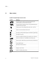
Страница 26: ... SekundenEDIT Knopfdrücken Druck erzeugen zum Teachen des Messwertes hier TP1 Symbol auf dem Display blinkt hier Out A Sicherheitscode aktiv Sperrung gegen unbefugte Programmierung Sicherheitscode inaktiv UP Taste A drücken weiterschalten umschalten im Menü UP Taste A oder DOWN Taste B drücken Wert einstellen Taste hier UP Taste und EDIT Knopf gleichzeitig drücken EDIT Knopfdrücken VerzweigungimMe...

Страница 27: ...SDE3 Festo SDE3 0604a Deutsch 27 Bild 23 EDIT Modus ...

Страница 28: ...SDE3 Festo SDE3 0604a Deutsch 28 Bild 24 TEACH Modus ...

Страница 29: ...SDE3 Festo SDE3 0604a Deutsch 29 1 2 1 Nur beim SDE3 D Angezeigten Eingangswert umschalten In A B 2 Nur beim SDE3 D Minimal Maximalwert von In B anzeigen löschen Bild 25 SHOW Modus ...

Страница 30: ...SDE3 Festo SDE3 0604a Deutsch 30 ...

Страница 31: ... Conditions of use 37 5 Installation 38 Mechanical installation 38 Pneumatic installation 39 Electrical installation 39 6 Commissioning 40 Symbols on the display 41 Preparing commissioning 43 Test run 48 7 Operation 49 8 Care and maintenance 49 9 Dismantling 50 10 Accessories 50 11 Trouble shooting 51 12 Technical specifications 53 13 Menu structure 55 Symbols for representing the menu structure 5...

Страница 32: ...ical connection 4 SDE3 for front panel mounting 5 Clamping plate for front panel mounting 6 Fastening slide rear 7 SDE3 D Compressed air or vacuum connection for In A and In B 8 SDE3 S Compressed air or vacuum connection for In A 9 SDE3 Z Compressed air or vacuum connections p1 and p2 for In A aJ Inscription label holder aA DOWN button B button aB UP button A button aC EDIT button aD Display Fig 1...

Страница 33: ...values in inches of mercury W values in inches of water Assemblyand connection HQ4 hat rail fastening QS4 connection WQ4 hat rail fastening with wall support QS4 connection FQ4 front panel mounting QS4 connection Electric outputs 2P 2 PNP outputs 2N 2 NPN outputs Electrical connection M8 plug M8 K cable 2 5 m with core end sleeves Connectingcable accessory G cable with socket SIM straight 2 5 m W ...

Страница 34: ... button twice SP field flashes 4 Set the desired switching point with the UP DOWN buttons 5 Hold the EDIT button pressed down for 3 s The SDE3 is then in the RUN mode In this way you can teach a switching point 1 Apply the first measuring pressure assignment see section 3 2 In order to accept the measured value as the teaching point TP1 for Out A press first the A button then also the EDIT button ...

Страница 35: ...ement B 2 Measuring pressure p1 Reference pressure p2 Fig 3 The SDE3 D offers in one device two inde pendently operating sensor elements A B to each of which a switching output Out A Out B is assigned The measurement of the input values In A In B at the pneumatic connections takes place with the aid of piezoresistive sensor elements with downstream switched elec tronic evaluating unit The measured...

Страница 36: ...e following specifications are always observed S Compare the maximum values specified in these operating instructions with your actual application e g operating media pressures forces torques temperatures masses speeds voltages S Take into consideration the ambient conditions at the location of use S Please comply with national and local safety laws and regulations S Remove all transport packing s...

Страница 37: ...emarks Fit the adapter plate e g 2 x M3 1 1 Hang the SDE3 onto the hat rail fastening plate and press until the fastening slide clips in Push the SDE3 into the recess 70 x 22 mm in the front panel Hang on the clamping plate and press until the fastening slide clips in Tighten the screws 2 3 Through hole 3 4 mm 1 Hole pattern see page 59 2 With a front panel of thickness 2 mm remove the washers if ...

Страница 38: ...nnection Electrical installation Warning S Use only power units which guarantee reliable electrical isolation of the operating voltage as per IEC DIN EN 60204 1 Observe also the general requirements for PELV power circuits as per IEC DIN EN 60204 1 Note Long signal cables reduce the immunity to interference S Make sure that the signal cable is not longer than 30 m S Connect the SDE3 as follows Pin...

Страница 39: ...he desired switching behaviour of the switching outputs Switching points SP and hysteresis Hy Settingthe threshold value comparator Settingthewindowcomparator With setting NO normally open contact P 1 0 Hy OUT SP Hy Hy P 1 0 OUT SP min SP max With setting NC normally closed contact P 1 0 SP Hy OUT P 1 0 OUT SP min SP max Hy Hy Fig 10 ...

Страница 40: ...haract of normally closed contact min max Extreme values Minimum maximuminput measured value In A B 1 Teach Teach mode active Option Option On Off measured value smoothing on off Lock Security code active blocked against unauthorizedparametrizing Special menu SPEC is active 1 RUN mode Graphic display of the current measured value related to the maximum measured value of the measuring range The lef...

Страница 41: ...ws input value In B Segment below right and B and min or max light up 1 SHOW mode active 7 segment display shows an extreme value of In B Marked segments light up SHOW mode active Diagnosis 7 segment display shows error number e g Er01 Marked segments light up and Option flashes EDIT mode active Special menu SPEC is open 7 segment display shows the set filter option Marked segments light up and Lo...

Страница 42: ... if the EDIT button is pressed for 3 s or if a monitoring time expires timeout see section 13 Menu structure S Switch on the operating voltage The SDE3 is then in the RUN mode S Check the functions of the SDE3 Note An overview of the menu structure can be found in section 13 RUN mode Shows the measured value relative pressure differential pressure and the signal status of the switching outputs Out...

Страница 43: ...riate error numbers will be shown when button A or B is pressed again see also section 11 The SHOW mode shows the following settings and values Settings for Out A B switching function threshold window comparator switching point SP or SP min and SP max hysteresis HY switching characteristic NO NC Extreme values of In A and In B In B only with SDE3 D minimum pressure value min maximum pressure value...

Страница 44: ...lowing can now be selected see also Fig 23 output the behaviour of which is to be set special menu SPEC for setting the options and the security code Lock 3 If you wish to set Out B press the B button DOWN Out B now flashes 4 In order to confirm the selected output press the EDIT button The currently set switching function now flashes 5 Select desired switching function threshold value window comp...

Страница 45: ...the EDIT button Out A flashes 3 Press the UP button until the menu SPEC Special is selected SPEC flashes 4 In order to confirm press the EDIT button Option flashes 5 Select the desired filter option ON OFF with the UP DOWN button ON Smoothing of the measured values In A B is active time constant approx 500 ms OFF Smoothing of the measured values In A B is inactive 6 In order to confirm press the E...

Страница 46: ...ing point TP1 or TP2 SPmax larger teaching point TP1 or TP2 Position of the teaching points example Position of the teaching points example Fig 14 For teaching the switching variables 1 Apply first measuring pressure relative pressure differential pressure p1 p2 2 In order to activate the TEACH mode and to accept the measured value as the first teaching point TP1 first press the button for the des...

Страница 47: ...ent Display delete minimum maximum value 1 By repeatedly pressing the A button UP or the B button DOWN you can display the current settings for a switching output Out A or Out B until the display min flashes The relevant minimum value smallest measured value of In A B will be shown symbols used in display of extreme values see Fig 12 2 In order to delete the minimum value press the EDIT button bri...

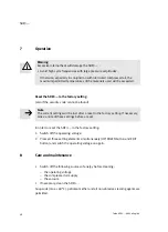
Страница 48: ...current settings will be lost after a reset to the factory setting If necessary make a note of these settings before a reset In order to reset the SDE3 to the factory setting 1 Switch off the operating voltage 2 Press all three setting elements simultaneously UP DOWN button and EDIT button and switch the operating voltage on again 8 Care and maintenance S Switch off the following sources of energy...

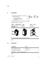
Страница 49: ... relevant connections from the SDE3 Dismantle the SDE3 as follows SDE3 HQ4 and SDE3 WQ4 SDE3 FQ4 Wall fitting or hat rail fastening 1 Plate fitting Front panel 1 2 1 First lift up the SDE3 1 Then tilt the SDE3 forwards 2 Fig 16 10 Accessories Designation Type Connecting cable 4 pin M8 SIM M8 4 D Adapter plate for wall fitting 1 SXE3 W 1 With SDE3 WQ4 included in delivery Fig 17 Fig 15 ...

Страница 50: ...ct pressure display Pneumatic connections swapped only with SDE3 D or SDE3 Z Connect tubing in accordance with section Pneumaticinstallation SDE3 operated with non permittedmedium Replace the SDE3 and operate only with compressed air Pressure display flashes or error number Er09 Er12 flashes Pressure outside measuring range Observe permitted pressure measuringrange Er12 flashes see also Fig 19 Exc...

Страница 51: ...uring range after exceeding not reaching i d i Er11 1 Value below measuring range with In B g g permitted maximum values replace SDE3 Er12 1 Measuring range exceeded with In B values replace SDE3 Er13 Er16 Reserved for extensions Er17 2 3 Undervoltage in the power supply Observe permitted operating voltage range 1 7 segment display flashes Error display in the SHOW mode see Fig 25 2 7 segment disp...

Страница 52: ...sired but should prevent the collection of condensate in the pressure sensor Operatingmedium Filtered lubricated or non lubricated compressed air filter fineness 40 m Indicatingrange bar 000 999 999 1 000 0 000 2 000 0 00 6 00 0 00 10 00 Accuracy FS 2 at T 20 25 C 3 at T 0 50 C Reproducibility FS 0 3 Setting range Switching values Hysteresis FS FS 0 100 0 90 Filter option Smoothing the input signa...

Страница 53: ...dapted to MZ MY ME coils Pulsed For all electrical connections Protection class IP65 as per EN 60529 Protection class III as per DIN VDE 0106 1 Interferenceimmunity Interference emission See conformity declaration www festo com Vibration resistance As per DIN IEC 68 EN 60068 part 2 6 0 35 mm travel at 10 60 Hz 5 g acceleration at 60 150 Hz Shock resistance As per DIN IEC 68 EN 60068 part 2 27 30 g...

Страница 54: ...n for 3 seconds Create pressure for teaching the measured value here TP1 Symbol on the display flashes here Out A Security code active blocked against unauthorized programming Security code inactive Press the UP button A switch further switch over in the menu Press the UP button A or the DOWN button B set value Press the button here UP button and EDIT button simultaneously Press the EDIT button Br...

Страница 55: ...SDE3 Festo SDE3 0604a English 55 Fig 23 EDIT mode ...

Страница 56: ...SDE3 Festo SDE3 0604a English 56 Fig 24 TEACH mode ...

Страница 57: ...SDE3 Festo SDE3 0604a English 57 1 2 1 Only with SDE3 D Switch over input value displayed In A B 2 Only with SDE3 D Display deleteminimum maximum value of In B Fig 25 SHOW mode ...

Страница 58: ...SDE3 Festo SDE3 0604a English 58 ...

Страница 59: ...SDE3 Festo SDE3 0604a 59 de Lochbilder Adapterplatte SXE3 W en Hole patterns adapter plate SXE3 W ...

Страница 60: ... ou reproduction de ce document sous quelque forme que ce soit et toute exploitation ou communication de son contenu sont interdites sauf autorisation écrite expresse Tout manquement à cette règle est illicite et expose son auteur au versement de dommages et intérêts Tous droits réservés pour le cas de la délivrance d un brevet d un modèle d utilité ou d un modèle de présentation Copyright E Festo...

Отзывы: