background image

A.      Technical  appendix

A−7

Festo  P.BE−SBO−Q−EN    en  0702a

A.3

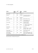
Siemens  star

Fig.A/1:

Siemens  star

The  Siemens  star  shown  here  is  a  helpful  model  for  roughly
setting  the  focus.

Содержание SBO Q Series

Страница 1: ...Manual Electronics Description Compact Vision System Type SBO Q Manual 548 319 en 0702a 715 318 Compact Vision System ...

Страница 2: ......

Страница 3: ...lic of Germany 2007 Internet http www festo com E mail service_international festo com Thereproduction distributionandutilisationofthisdocument as well as the communication of its contents to others without express authorisation is prohibited Offenders will be held liablefor payment of damages All rights reserved in particular the right to register patents utility models and designs ...

Страница 4: ... general instructions II Festo P BE SBO Q EN en 0702a Trademarks Harax is a registered trade mark of HARTING Electronics GmbH Co KG Harting RJ Industrial is a registered trade mark of HARTING Electronics GmbH Co KG ...

Страница 5: ... and connecting elements 1 8 1 3 Software packages 1 10 1 4 Accessory 1 11 1 5 Selection of a lens for SBOC 1 13 1 6 Lighting selection 1 17 2 Fitting 2 1 2 1 Fitting 2 3 2 1 1 Connecting the Compact Vision System 2 4 2 1 2 Dimensions of the SBO Compact Vision System 2 5 2 1 3 Mounting with adapter kit type SBOA HMSV 39 2 6 2 1 4 Mounting dismantling of lens and protective tubing for SBOC 2 7 2 1 ...

Страница 6: ... 8 1 I O features for evaluation mode triggered 4 18 4 8 2 I O features for evaluation mode free run 4 24 4 8 3 I O features for evaluation mode fixed frame rate 4 28 4 9 Connecting the device to a higher order controller PLC IPC 4 33 4 9 1 General information about the use of inputs 4 34 4 9 2 General information about the use of outputs 4 36 4 9 3 Use of internal I Os 4 37 4 9 4 Use of the I O e...

Страница 7: ...gister A 12 A 6 2 Output register A 13 A 6 3 Fast access to input and output register A 14 A 6 4 Extended system status system information A 14 A 6 5 Device system time A 15 A 6 6 Total type tolerance in the current test program A 16 A 6 7 Basic results of the last test A 17 A 6 8 Features Results of the last test A 18 A 6 9 System parameters A 21 A 6 10 Example of program A 22 B Index B 1 B 1 Ind...

Страница 8: ...Contents and general instructions VI Festo P BE SBO Q EN en 0702a ...

Страница 9: ...y be used as follows only in an industrial environment as intended in original status without unauthorized modifications Only the conversions or modifications described in the documentation supplied with the product are permitted in perfect technical condition When used together with conventional accessory compo nents such as sensors and actuators the specified limits for pressures temperatures el...

Страница 10: ...ion of conformance Product designs which are marked with the following symbol fulfil the requirements of the Recognized Component Marks for Canada and the United States Only for use in Class 2 circuits Note Note the following if your application must comply with the specifications of the Recognized Component Marks for Canada and the United States Rules for complying with the UL certification can b...

Страница 11: ...ch as barricades and warning signs Caution Electrostatically sensitive components Electrostatic discharges can damage the internal electronics Do not open the housing Observe the handling specifi cations for electrostatically sensitive devices Caution A dirty and scratched lens or a dirty and scratched safety window can lead to visual defects Make sure that the safety window lens are not scratched...

Страница 12: ... the Compact Vision System in a well ventilated location especially screened from the heat emitted by other devices and from sources of light Service Please consult your local Festo repair service if you have any technical problems Target group This description is intended exclusively for technicians trained in control and automation technology who have ex perience in installing and commissioning ...

Страница 13: ...between the following danger warnings Warning This means that failure to observe this instruction may result in serious personal injury or damage to property Caution This means that failure to observe this instruction may result in personal injury or damage to property Note This means that failure to observe this instruction may result in damage to property The following pictogram marks passages i...

Страница 14: ...ns tips and references to other sources of information Accessories Information on necessary or sensible accessories for the Festo product Environment Information on environment friendly use of Festo products Text markings The bullet indicates activities which may be carried out in any order 1 Figures denote activities which must be carried out in the numerical order specified Hyphens indicate gene...

Страница 15: ...nd operating the Compact Vision System Additional information on commissioning parameterizing and diagnosing with the software packages can be found in the software package help systems Type Title Contents Electronics description this description Compact Vision System type SBO Q Connecting installing and operat ing the Compact Vision System Help system for the CheckKon software CheckKon Help Funct...

Страница 16: ...ti Software package for creating test programs CMOS sensor Opto electronic sensor which converts light signals into electric signals In addition to the pure sensor function functions for image conversion are built into the chip e g lighting check and contrast correction CP cable Special cable used to connect the various CP modules in a CP string CP connection Socket or plug on the CP modules which...

Страница 17: ...he time during which the CMOS sensor is exposed to light during record ing The longer the exposure time the more light will penetrate The choice of exposure time depends e g on the movement speed the light available and the light sensitivity of the sensor see also sensor gain With moving objects excessive exposure times result in blurred pictures Falling edge Transition from logical 1 to logical 0...

Страница 18: ...k properties and firmware Sensor gain Influences the light sensitivity of the sensor If the gain is increased the light sensitivity will also be increased Excessive gain can lead to grainy pictures Status controlled The detection of a signal e g input reacts to a logical 1 or logical 0 String allocation Type and sequence of the CP modules connected to one or more CP strings TCP IP Combination of t...

Страница 19: ...System summary 1 1 Festo P BE SBO Q EN en 0702a Chapter 1 ...

Страница 20: ...tem summary 1 1 1 1 Structure of the SBO Compact Vision System 1 3 1 2 Variants 1 5 1 2 1 Mode of operation 1 7 1 2 2 Display and connecting elements 1 8 1 3 Software packages 1 10 1 4 Accessory 1 11 1 5 Selection of a lens for SBOC 1 13 1 6 Lighting selection 1 17 ...

Страница 21: ...ices for type SBOI a built in lens and built in LED lighting for type SBOC a standardised C mount lens socket matching lenses as well as optical accessories such as filters and other lens elements are available on request Function The Compact Vision System SBO Q allows visual test functions to be integrated at low cost in your machines and systems for analyzing parts for quality and position The c...

Страница 22: ...ectly to the PC via the Ethernet interface Evaluations can be controlled via digital I Os or by a PC 1 Compact Vision System here type SBOC 2 PC with software packages 1 2 Fig 1 1 Direct networking with the PC 1 2 3 1 Hub switch 2 PC with software packages 3 Compact Vision System here type SBOC Fig 1 2 Camera network ...

Страница 23: ... Monochrome Colour Tab 1 1 Type codes Design Features Advantages application area SBOI Q R1B CMOS sensor resolution 640 x 480 pixels inch mono chrome Interfaces Ethernet digital I Os and CAN Integrated lens Integrated LED lighting Protection classes IP65 and IP67 Especially suitable for short range work ţ 22 mm to approx 1000 mm longer ranges lead to loss of sharpness Integrated lighting for dista...

Страница 24: ...e photo graphic properties can be used Filters and lenses per object lens SBOC Q R1C Like type SBOC Q R1B but CMOS sensor in colour SBOC Q R2B Like type SBOC Q R1B but CMOS sensor with resolution 1280 x 1024 pixels 2 3 inch monochrome SBOC Q R2C Like type SBOC Q R1B but CMOS sensor with resolution 1280 x 1024 pixels 2 3 inch in colour 1 Only in conjunction with protective tubing supplied 2 Lenses ...

Страница 25: ...processing functions are built into the operating system firmware of the device Communication The Compact Vision System can communicate via the net work with the PC or with a PLC by means of the Ethernet in terface Other I O options are available via the CAN interface Commissioning For commissioning and operation the corresponding soft ware packages are used see also chapter 1 3 ...

Страница 26: ...N interface 4 Ethernet interface 5 Power supply and digital I Os 6 Focus adjustment 1 2 3 4 5 6 Fig 1 3 Display and connecting element type SBOI Q 1 Adapter for protective tubing 2 Protective tubing 3 Lens on request 4 Status LEDs 5 CAN interface 6 Ethernet interface 7 Power supply and digital I Os 1 2 3 4 5 7 6 Fig 1 4 Display and connecting elements type SBOC Q ...

Страница 27: ...s I O circuitry 2 digital inputs and 3 digital outputs Ethernet Plug M12x1 4 pin d coded For pin allocation see Tab 3 6 Ethernet interface Communication with higher order devices e g the PC or PLC Data output e g analysis data etc Bus Plugs M12x1 5 pin For pin allocation see Tab 3 7 CAN interface for extending the I O functionality of the device Tab 1 4 Connections of the Compact Vision System ...

Страница 28: ...vides the following functions Theme Function Configurationand commissioning Defining the signal reaction Defining the picture sampling rate sensor amplification Defining the evaluation and output functions Analysis Display of evaluated parts live pictures statistics and handling of test programs Diagnostics Display of device characteristics Display of faults Service Documentation of a system Tab 1...

Страница 29: ...M12x1 4 pin Socket M9x0 5 5 pin Socket M12x1 5 pin KVI CP 3 Connecting cable Cable for coupling of external I O modules in conjunction with cable SBOA K20CP SUP CP A04 M12 CL I O module Output module with 4 digital outputs 4 female connectors M12 5 pin CP E08 M12 CL I O module Input module with 8 digital inputs 8 female connectors M12 5 pin SBOA HMSV 39 Adapter BS Adapter kit for fitting with scre...

Страница 30: ...he adapter possesses an internal thread G 1 4 for for fastening to commercially available photo video tripods SBOL 12 SBOL 25 Lens Lens Standard lens focal depth 12 mm Standard lens focal depth 25 mm SBOL C 5 Adapter 5 mm spacer ring CS mount to C mount SBOL IP 50 Cylinder barrel BG Protective tubing Tab 1 6 Accessory ...

Страница 31: ...ens diameter is 38 mm The maximum possible length of the lens from the front edge of the lens to the flange surface of the thread side is 42 mm Note Note that with most lenses the lens length changes when the focus is re adjusted The setting infinite usually leads to the shortest lens dimension Operation without protective tubing If you remove the protective tubing and the adapter you can use lens...

Страница 32: ...e camera and the object to be photographed can be calculated according to the laws of optics Note that the following calculation for mula describes the distance between the so called main level and the object to be represented With a thin lens element the main level is the centre of the lens With a lens the position of the main level cannot be so easily determined As an estimate you can assume the...

Страница 33: ...be obtained by multiplying the horizontal field of vision by 0 75 480 640 or 0 8 1024 1280 Examples for SBO Q R1 A lens with focal depth 12 generates a field of vision approx 100 mm wide at a work distance of 200 mm with SBO Q R1 A lens with focal depth 25 generates a field of vision approx 100 mm wide at a work distance of 400 mm with SBO Q R1 The following diagrams see Fig 1 5 can be used to mak...

Страница 34: ...summary 1 16 Festo P BE SBO Q EN en 0702a SBO Q R1 SBO Q R2 1 2 3 1 2 3 1 Focal depth 35 mm 2 Focal depth 25 mm 3 Focal depth 12 mm Fig 1 5 Work distances g mm and object size G mm for typical fixed focal depths ...

Страница 35: ... external lights to the output O2 of the device The lighting is then controlled by the device Observe the correct system parameter configuration here Observe the maximum residual current at the outputs The used light source for lighting the inspection parts has a major influence on the image quality Often inappropriate light sources are used Which light source is appropriate for your application m...

Страница 36: ...ch hits at an angle produces diffuse reflection which allows slight differentiations to be made For glossy surfaces a polarization filter is recommended Faulty contact galvanization Edges of thin transparent inspection parts Wide anglelight Throws direct light at a wide angle onto the edges of the inspection parts angled illumination of the surface edges This clearly accentuates the edges of the i...

Страница 37: ...Fitting 2 1 Festo P BE SBO Q EN en 0702a Chapter 2 ...

Страница 38: ...2 3 2 1 1 Connecting the Compact Vision System 2 4 2 1 2 Dimensions of the SBO Compact Vision System 2 5 2 1 3 Mounting with adapter kit type SBOA HMSV 39 2 6 2 1 4 Mounting dismantling of lens and protective tubing for SBOC 2 7 2 1 5 Dismantling the protective foil for SBOI 2 8 ...

Страница 39: ...n System in a well ventilated location especially screened from the heat emitted by other devices and from sources of light Note The Compact Vision System may be damaged if it is not handled correctly Make sure that glass surfaces and lenses are not scratched or dirty Mount the Compact Vision System so that items passing by do not touch the device Note Use screening e g opaque black housing agains...

Страница 40: ...pter 4 6 On the bottom of the device there is a mounting profile with a dovetail guide The following adapter kits can be used for mounting Type Designation Description SBOA HMSV 39 Adapter BS Adapter kit for mounting with screw on adapter plate included in the adapter kit SBOA HMSV 40 Adapter BS Adapter kit for mounting with screw on adapter plate e g adapter plate type HMSV 11 not included in the...

Страница 41: ...2 Fitting 2 5 Festo P BE SBO Q EN en 0702a 2 1 2 Dimensions of the SBO Compact Vision System 1 1 Principal axis Fig 2 1 SBOI dimensions 1 1 Principal axis Fig 2 2 SBOC dimensions with protective tubing ...

Страница 42: ...e SBOI as an example 2 3 4 1 2 1 Dovetail of the Compact Vision System 2 Clamping devices 3 Hole for M5x16 socket head screw with centring sleeve 4 Adapter plate Fig 2 3 Mounting with adapter kit type SBOA HMSV 39 Proceed with mounting as follows Place the Compact Vision System so that the field of vision is unhindered and the LEDs on the rear of the housing can be seen Tighten the mounting screws...

Страница 43: ...tective tubing Attaching the lens If necessary remove the protective covers from the lens and from the camera housing Carefully place the lens in the fixture of the camera hous ing and tighten it by hand by turning it in a clockwise direction Attaching the protective tubing Before attaching the protective tubing Check that the seal has a good fit on the protective tubing Carefully place the protec...

Страница 44: ...g the lens Turn the lens in a counterclockwise direction and pull it forwards out of the mounting Attach the protective covers to the lens and to the camera housing 2 1 5 Dismantling the protective foil for SBOI To protect against scratches or contamination during trans portation and mounting a protective foil has been applied to the front side of the safety window on devices of type SBOI Carefull...

Страница 45: ...Installation 3 1 Festo P BE SBO Q EN en 0702a Chapter 3 ...

Страница 46: ...allation 3 1 3 1 General installation instructions 3 3 3 1 1 Selecting the power supply unit 3 5 3 2 Electrical connections 3 6 3 2 1 Connecting the operating voltage and I Os 3 6 3 2 2 Connecting the Ethernet interface 3 11 3 2 3 Connecting the CAN interface 3 15 ...

Страница 47: ...first The technical specifications in this documentation may show deviating values Warning Sudden unexpected movements of the connected actua tors can cause personal injury and damage to property Before carrying out installation and maintenance work switch off the following Operating and load voltage supplies Any other sources of energy e g the compressed air supply Caution Lines with high levels ...

Страница 48: ...that the cable lengths specified in the following table are always complied with Line type Permitted line lengths Signal cables max 30 m Supplylines max 10 m Tab 3 1 Maximum permissible line lengths Note Check within the framework of your EMERGENCY STOP circuit to ascertain the measures necessary for putting your machine system into a safe state in the event of an EMERGENCY STOP e g switching off ...

Страница 49: ... EN 60204 1 By using PELV circuits protection against electric shock protection against direct and indirect contact is guaranteed in accordance with IEC DIN EN 60204 1 electrical machine equipment general requirements Recommendation Use a separate regulated power supply which does not have to supply any other devices You will then achieve the greatest resistance to interference Simple 24 V transfo...

Страница 50: ...I Os plug M12x1 1 2 3 Fig 3 1 Electrical connections of the Compact Vision System type SBO The following connection options are available see also chapter 4 9 and Tab 4 4 3 2 1 Connecting the operating voltage and I Os Caution Damage to components Make sure that the max permissible operating voltage range is not exceeded see Technical Data in appendix A 4 Protect the power supply of the Compact Vi...

Страница 51: ... for power supply straight socket M12x1 8 pin core ends tin plated Tab 3 2 Cable for power supply and digital I Os The operating voltage is fed together with the input output circuit via the 8 pin M12 plug marked 24 V DC see also Tab 3 3 The following components are supplied with 24 V DC via this connection the internal electronics of the Compact Vision System the load current of activated outputs...

Страница 52: ...n resulted in bad part 4 red RD Metal covering 5 Screen shield 1 Tighten union nut by hand 2 Core colours of the original cable type SIM M12 8GD PU 3 The signal levels edges can be configured via the system parameters The given description corresponds to the standard configuration 4 The function can be configured via system parameters The given description corresponds to the standardconfiguration ...

Страница 53: ... Ready for operation logical 1 Function at O1 Good part logical 1 Function at O2 Bad part logical 1 Tab 3 4 System parameters with standard configuration Please note that the tolerance of 24 V DC 10 must be complied with the power supply of the Compact Vision System must be protected externally Fast acting 2 A micro fuse the residual current of all outputs must not exceed 1 5 A the cable screening...

Страница 54: ... BE SBO Q EN en 0702a 1 2 AC DC 2A 24 V I0 Triggersignal O0 Ready for operation O1 Good part O2 Bad part GND 2 1 6 4 8 7 S1 1 External fuse 2 Cable screening Fig 3 2 Example of a system parameter configuration with default values ...

Страница 55: ...firewall Note When the camera is actively connected to the network large amounts of data may be sent depending on the operation mode Due to this the network between the PC and cameras is correspondingly heavily loaded Therefore it is preferable to have a direct connection if possible If in doubt ask your network administrator whether appropriate bandwidths are available for you or what an optimum ...

Страница 56: ...f the PC does not support automatic adaptation of the transmitting and receiving lines AUTO MDI X This accessory is commercially available Tab 3 5 Cable for the Compact Vision System type SBO For special requirements for use in an industrial environment use a screened flexible Ethernet round cable of category 5 which will fulfil your requirements with regard to oil resistance bending radius permis...

Страница 57: ... side of the Compact Vision System M12 plug 1 Pin Signal Description 1 2 1 TD Transmitted data 1 2 2 RD Received data 3 TD Transmitted data 4 3 4 RD Received data Metal covering Screen shield 1 d coded Tab 3 6 Pin assignment of the Ethernet interface The Ethernet interface of the Compact Vision System complies with standard 10BaseT 100BaseTX for 100 Mbit networks Note Use a screened plug connector...

Страница 58: ...the routers aren t configured accordingly the devices cannot be found using the search function If in doubt ask your network ad ministrator Direct connection with the PC If the network connection of the PC does not support automatic adaptation of the transmitting and receiving line AUTO MDI X you will also require in addition to the original cable a cross over cable and a cable coupling see also T...

Страница 59: ...e the notes on installation and commissioning in section 4 9 5 M12 plug Pin Signal 1 2 1 n c not connected 2 4 2 n c not connected 3 GND 5 3 4 CAN_H 3 5 CAN_L Tab 3 7 Pin assignment of the CAN interface bus The device does not feed any supply current into the CP string and it also does not take any supply current from the CP string The functional principle of the CAN interface depends on the syste...

Страница 60: ...3 Installation 3 16 Festo P BE SBO Q EN en 0702a ...

Страница 61: ...Commissioning 4 1 Festo P BE SBO Q EN en 0702a Chapter 4 ...

Страница 62: ...4 8 Selection of the evaluation mode 4 17 4 8 1 I O features for evaluation mode triggered 4 18 4 8 2 I O features for evaluation mode free run 4 24 4 8 3 I O features for evaluation mode fixed frame rate 4 28 4 9 Connecting the device to a higher order controller PLC IPC 4 33 4 9 1 General information about the use of inputs 4 34 4 9 2 General information about the use of outputs 4 36 4 9 3 Use o...

Страница 63: ... the CheckKon software package See also CheckKon Help Use the SBO DeviceManager for changing network settings on the device Create test programs with the CheckOpti software package See also CheckOpti Help The commissioning steps are usually taken in the sequence of the following chapters For optimising the system it may be necessary to repeat steps which have already been carried out ...

Страница 64: ... is part of the CheckKoninstallation Note Administrator rights are required for installing the software packages You can install the software packages from the CD ROM as follows 1 Close all programs 2 Place the corresponding Festo CD in your CD ROM drive If Auto Run is activated on your system installation will start automatically and you can skip steps 3 and 4 3 Select Execute in the start menu 4...

Страница 65: ...nnection can be found on the Windows control panel under Network and Dial up Connections The available LAN connections are displayed there Select the LAN connection with which you would like to establish a connection to the device and have its prop erties displayed Fig 4 1 Network and dial up connections Check in the window Local Area Connection properties especially the properties of the entry In...

Страница 66: ...he DHCP server must be reachable via the network connection If this isn t the case e g when there is a direct connection to the camera the network connection must be told which IP address is to be used see Fig 4 2 The settings of the PC network connection and the camera must match Select different IP addresses which are not assigned to other network devices see Tab 4 1 Via the sub network mask sel...

Страница 67: ... networkmask 255 255 0 0 255 255 0 0 Tab 4 1 Example of suitable network settings Further information can be found in chapter 4 4 and appendix A 2 Note The following address is set on the Compact Vision System when it leaves the factory 192 168 2 10 Note Start the PC again if network settings have been modified ...

Страница 68: ... connection to the device Device search function The SBO DeviceManager has a search function This search function allows a connection to be established to devices for which there is no known network address The search func tion uses a special Ethernet procedure Multicast With this procedure messages can be transmitted simultaneously to several slaves or to a closed group of slaves For this process...

Страница 69: ...network nodes are enabled for multicast Check the set search range and search duration in the SBO DeviceManager If you aren t successful Connect the device directly to your PC if possible By doing this you rule out incorrect network configurations Also the search function will find the device even if the set ting Visibility in search requests is set to Local 1 router ...

Страница 70: ...d if the IP address is to be assigned automati cally via DHCP DHCP stands for Dynamic Host Configuration Protocol The DHCP server manages a range of IP addresses and assigns them to the DHCP compatible terminals Specify fixed IP address If you are not using a DHCP server you must specify a fixed IP address Make sure here that the IP address and the network mask of the devices match the network set...

Страница 71: ...ymbol on the Windows Desktop Or in the case of a standard installation In the Windows Start menu select the entry Festo Software Festo CheckKon The program opens the dialog window Welcome to CheckKon Start dialog In this dialog window configure the connection to the compact camera 3 Select the entry via Ethernet interface from the Connect selection Confirm this selection by clicking on Next 4 In t...

Страница 72: ...et support for setting the image and lighting control parameters Now carry out the following steps 1 Switch the lighting on and direct these toward the test area If the lighting is controlled by the device make the corre sponding system parameter settings for the lighting control 2 Roughly adapt the following image parameters so that an image of the test area can be identified Viewing area change ...

Страница 73: ...C with standard lens from Festo Use a screwdriver to turn the focus adjuster on the rear side of the camera housing Loosen the locking screw on the lens In order to focus the object turn the focusingring Tighten the locking screw again slightly Tab 4 2 Setting the focus 6 For devices of type SBOC Set the aperture of the lens so that there is sufficient light available to the sensor Type SBOI Type ...

Страница 74: ...ighting is optimally aligned when the inspection part properties to be tested are enhanced with maximum con trast 8 Now carry out an iterative optimisation of all steps and settings To do this repeat steps 4 to 7 The optimum setting is reached when the inspection part properties to be tested are sharply displayed in the camera image and are brought out with maximum contrast ...

Страница 75: ... system parameters into account The inspection of workpieces is done based on the image Pre processing 3 Switch the display of the various images in the Live Image window on and off The pre processing steps must be configured in CheckKon in the Live Image window so that the properties to be tested are reliably shown in the image Pre processing 3 Furthermore the pre processing should remove the ima...

Страница 76: ...r inspection part can greatly increase For this reason image optimisation with respect to the tested prop erties should always be attempted before pre processing e g by optimising the type and position of the lighting position of the camera position of the test part optical properties lens filter etc See also chapter 4 6 ...

Страница 77: ...can be selected via the system parameter Evaluation mode in the CheckKon System parameters window Triggered Single image recording and check at every valid trigger signal Free run Continuous image recording and testing without fixed frame rate as long as the trigger signal is applied Fixed frame rate Continuous image recording and testing with fixed frame rate as long as the trigger signal is appl...

Страница 78: ... test results are output after the test is finished Afterwards the device starts immediately with the next test Fixed frame rate Test of endless parts at constant speed The trigger signal is permanently applied The test results are output after the test is finished The device starts the next test according to the defined frame rate 4 8 1 I O features for evaluation mode triggered In the evaluation...

Страница 79: ...tion is finished at the earliest The output time can be delayed by prolonging the trigger signal The outputs in this case are only written when the signal at the input trigger signal has been taken back This way the higher ordered controller PLC can signalise its readiness to accept the results of the workpiece inspection Also set the output time and output duration via the following system parame...

Страница 80: ...psed and the signal at the input trigger signal of the next started cycle has been withdrawn With the above mentioned conditions it is possible to define minimum times for evaluation and output as well as to influ ence their starting times A higher ordered controller PLC IPC can thus start a new cycle and only then read the results of the previous cycle A high evaluation rate can be achieved with ...

Страница 81: ...mage evaluation long Trigger short B2 Image evaluation short Trigger long Trig ignored wait O0 1 Wait for trigger I0 0 Write outputs Write outputs B1 Output valid B2 Output valid Output invalid Internal outputs O1 O2 LED D Fig 4 3 Evaluation mode triggered Signal curve for standard settings System parameter settings default values Earliest start of output after trigger 0 ms Ignore trigger signal a...

Страница 82: ...ng Trig ignored wait O0 1 Cycle duration Wait for long trigger output wait for next trigger Trig ignored wait Trig ignored wait B1 Image evaluation Write outputs Write outputs Wait until B2 Image evaluation Wait until Wait I0 0 Output invalid B1 Output valid B2 Output valid B1 lighting B2 lighting Outputs external internal O1 LED D CP I Os Easy IP Fig 4 4 Evaluation mode triggered Signal curve usi...

Страница 83: ...gnored wait Trig ignored wait B1 Image evaluation short Write outputs Write outputs Wait until end Output invalid B1 Output valid B2 Output valid B1 lighting B2 lighting Trigger ignored wait O0 1 B2 Image evaluation long Trigger Outputs external internal O1 LED D CP I Os EasyIP Fig 4 5 Evaluation mode triggered Signal curve using system parameters 2nd case System parameter settings 1 Earliest star...

Страница 84: ...mains activated as long as logical 1 is at the trigger signal input status controlled During this time images are generated and evaluated cyclically Sequence The image evaluation starts with the beginning of the cycle During image evaluation the output ready for operation signalises a logical 0 The start of image generation and the control of the lighting can be defined with respect to the time of...

Страница 85: ...ed In this case the output ready for operation goes to logical 1 after outputting the results for the set duration The higher ordered controller PLC can now read the valid applied results If the trigger signal input still indicates logical 1 after the set duration has elapsed the next evaluation is started The results are only written to the outputs when the device is finished with the image evalu...

Страница 86: ...nvalid Internal outputs O1 O2 LED D B2 Image evaluation long Cycle duration Trig ignored wait O0 1 B3 Image evaluation short Write outputs B1 output B2 output B3 output Fig 4 6 Evaluation mode free run Signal curve for standard settings System parameter settings default values Earliest start of output after beginning of cycle 0 ms Ignore trigger signal after ready for operation 0 ms Start image ev...

Страница 87: ...B1 Image evaluation short Write outputs Write outputs Wait Output invalid Outputs external internal O1 LED D CP I Os EasyIP B1 Output valid B2 Output valid B1 lighting B2 lighting Trigger ignored wait O0 1 B2 Image evaluation long Immediate start of the evaluation since trigger still 1 Fig 4 7 Evaluation mode free run Signal curve using system parameters System parameter settings 1 Earliest start ...

Страница 88: ...mode fixed frame rate In the fixed frame rate evaluation mode the mode remains activated as long as logical 1 is at the trigger signal input status controlled During this time images are generated with a preset cycle duration During evaluation the output ready for operation shows a logical 0 The start of image generation and the lighting begins with the cycle start Only the duration of the lightin...

Страница 89: ...st here This evaluation mode is especially suitable for time critical tests in which the inspection part cannot be stopped or where a constant test rate is required e g for endless material testing Intermediate image storage should only be used to compen sate for fluctuations in the evaluation duration The frame rate should not be chosen higher than the average evaluation duration If the evaluatio...

Страница 90: ...O2 LED D B1 short evaluation Constant cycle duration Trig ignored wait O0 1 Wait until last evaluation is complete Write outputs B1 output B2 output B3 output B2 Image generation corresponding to cycle B3 Image generation corresponding to cycle B2 long image evaluation Actual asynchronous image evaluation B3 short evaluation Fig 4 8 Evaluation mode fixed frame rate Signal curve for standard settin...

Страница 91: ...B1 short evaluation Constant cycle duration Trigger ignored wait O0 1 Wait until last evaluation is complete B3 short image evaluation B1 output B2 output B3 output B2Imagegeneration correspondingtocycle B3Imagegeneration correspondingtocycle B2 long image evaluation Actual asynchronous image evaluation Wait until end Wait until end Output invalid Wait until end Fig 4 9 Evaluation mode fixed frame...

Страница 92: ...s these contain no jitter run times or system related delay times The duration for the write operation of the outputs and thus the duration for an invalid output state cannot be determined when external outputs are used I O extension device as CPI module EasyIP or CheckKon If the external outputs are deactivated by the system parameters and if only internal outputs are used this duration is approx...

Страница 93: ...gnal Accept input signal Acknowledge error signal Test program preselection Ready for operation Fundamental test results with identified part type Warning and error status Communication via Ethernet interface with EasyIP protocol Triggersignal Accept input signal Acknowledge error signal Test program preselection System parameters Test program tolerances Ready for operation Warning and error statu...

Страница 94: ...ts with signal function and other inputs Inputs with signal function These inputs depend on the output mode edge or status controlled They are read constantly If the signals are valid with regard to the current operating state the correspon ding action is immediately executed Inputs with signal function include Trigger signal Accept input signal Acknowledge error signal Other inputs These inputs a...

Страница 95: ...put signal input The accept input signal tells the device to read normal in puts The accept input signal is detected with edge control and is only valid when the output ready for operation out puts logical 1 In order to reread inputs the signal then must first be reset As long as inputs are read and processed e g loading of a new test program the output ready for operation is at logical 0 During t...

Страница 96: ...mera via the acknowledge error signal input If a warning status is signaled e g at the warning output this doesn t have to be acknowledged with the acknowledge error signal The warning status is automatically lifted when the cause is eliminated Error information description and suggestions for elimination can be found in chapter 5 1 2 4 9 2 General information about the use of outputs All outputs ...

Страница 97: ...le to the I Os I O Function I0 Triggersignal Polarity rising falling edge or logical 1 logical 0 can be changed via system parameters I1 Accept input signal or in case of error acknowledge error signal Polarity rising falling edge or logical 1 logical 0 can be changed via system parameters O0 Ready for operation O1 Allocation of the function to be output can be configured via system parameters e g...

Страница 98: ...installation Only the following I O modules are permitted in each case only one per Compact Vision System Output module CP A04 M12 CL 4 digital outputs Input module CP A04 M12 CL 8 digital inputs I O modules require operating voltage and load voltage supplies The Compact Vision System does not provide any operating voltage and load voltage supply for external I O modules To provide power to the ex...

Страница 99: ...um expansion Connect the modules in the following sequence Compact Vision System output module or Compact Vision System input module or Compact Vision System output module input module The 0 V line of cable SBOA K20CP SUP 2 is connected electri cally to the 0 V line of the Compact Vision System 1 Use suitable measures in order to avoid equalizing currents e g a common power unit for the compact ca...

Страница 100: ...N interface to Out Conclude the CheckKon program 2 Switch the device off in order to avoid faults or damage Disconnect the power supply to the device and the modules 3 Connect cables to the device and the modules as shown in Fig 4 10 4 Switch on the power supply again for the device and the modules 5 Make a connection to the device with the CheckKon program and set the system parameter Function at...

Страница 101: ...ions to the individual I Os of the module is fixed Input module CP E08 M12 CL I0 Ū 27 of the module is interpreted as a byte value and corresponds to the test program selection 0 Ū 255 0 test program 1 Output module CP A04 M12 CL O0 Ū 3 of the module is interpreted as a byte value and corresponds to the detected part type 0 Ū 15 0 part type 1 Additional information about the process and signal cur...

Страница 102: ...e Notes on installation To connect the device to a CP string use a suitable cable Cable SBOA K20CP WS from Festo is suitable Note Compact Vision Systems can only be operated on string 1 or 3 Operation on other CP strings is not supported at present The device does not have any ongoing CP connection and can only be connected at the end of a CP string string 1 or 3 The 0 V line of the Compact Vision...

Страница 103: ...Kon program 2 Switch the system off in order to avoid faults or damage Disconnect the power supply for the device and the CPX terminal 3 Connect the Compact Vision System to CP string 1 or 3 4 Switch on the power supply for the device 5 Make a connection to the device with the CheckKon program and set the system parameter Function at CAN interface to CPI module 6 Now connect the power supply for t...

Страница 104: ...addressed by a higher order controller which is either integrated in the CPX terminal e g CPX FEC from Version R5 or is connected to the higher order fieldbus To do this the associated CPX terminal must also be connected to the same fieldbus e g to PROFIBUS via the CPX module CPX FB13 from Version R12 Additional information about CP and CPX can be found in the CPI system description P BE CPX CP Ad...

Страница 105: ...masters without extended functions I O I O Compact Vision System acts as CP input and output module SBO yes 16 16 16 16 Tab 4 6 Allocated I Os for the CP input and output module Note The input and output numbers specified here must be con verted according to the above address assignment for the corresponding CP string number and sting allocation 16 CP inputs from the camera s point of view these a...

Страница 106: ...15 not used Tab 4 7 CP inputs 16 CP outputs from the camera s point of view these are inputs Output Function Bit O0 Triggersignal Bit O1 Accept input signal Bit O2 Acknowledge error signal Bit O3 Ū 7 not used Bit O8 Ū 15 Test program preselection is read after bit O1 1 Tab 4 8 CP outputs The address assignment depends on a the used CPX fieldbus node or CPX FEC b the used string number c the CP mod...

Страница 107: ... OO8 Ū O23 are assigned to the 16 outputs of the device O24 Ū O31 unassigned The address O8 therefore corresponds to the trigger signal Information about the process and signal curve can be found in chapter 4 8 CPX FEC controller The device can be controlled via the CPI module function of a CPX FEC Appropriate system programs can be transferred to the controller CPX FEC with the aid of the Festo F...

Страница 108: ...erfaces can be found in the descrip tions for the product concerned Reading and writing is done via the data packages assigned by EasyIP whereby the data to be read written is defined by memory addresses The device not only provides I Os via memory addresses but also allows access to the results of a test and to the settings of the system parameters Certain memory addresses can be read and written...

Страница 109: ...face to EasyIP 5 Set the IP address of the camera in the device to be connected 6 The device to be connected must now be programmed accordingly in order that it can access data of the camera Additional information about inputs can be found in chapter 4 9 1 The available memory addresses their function and an example of a program for FST can be found in appendix A 6 ...

Страница 110: ...nputs Test programs which are on the device can be update using the following system parameters in the section System Operation modes Teach mode Teach mode Part type Part orientation A test program must be updated as soon as system parameters which influence the creation of the picture and picture pro cessing are modified System parameters in the following sections belong here evaluation lighting ...

Страница 111: ...reated and evaluated with the CheckOpti software package The created test pro grams can then be transferred to the device with CheckOpti or CheckKon Additional information for creating test programs can be found in the CheckOpti Help If necessary please consult your local Festo Service ...

Страница 112: ...shed it is imperative that the following items be checked again Energency Stop circuits and function Wiring Control program Reliability of the results for various inspection parts Reliability of the results for various extraneous light conditions Save the data of the software packages as files ...

Страница 113: ...tems connected to the Compact Vision System If the permitted temperature range is exceeded this will be detected by the internal electronics and will lead to a error status Caution Further heating beyond this point can lead to uncontrolled malfunctions Make sure that the max permitted temperature range is not exceeded see Technical Data ...

Страница 114: ...4 Commissioning 4 54 Festo P BE SBO Q EN en 0702a ...

Страница 115: ...Diagnosis and error treatment 5 1 Festo P BE SBO Q EN en 0702a Chapter 5 ...

Страница 116: ...5 Diagnosis and error treatment 5 2 Festo P BE SBO Q EN en 0702a Contents 5 Diagnosis and error treatment 5 1 5 1 General diagnosis options 5 3 5 1 1 Status display 5 3 5 1 2 Error treatment 5 6 ...

Страница 117: ...ision System supply the status information listed in the followingsection 5 1 1 Status display The visual indicator of the operating statuses is shown via LEDs Ready status LED A LED Sequence Status Meaning error treatment LED flashing green ON OFF Device is ready for operation LED illuminated in red ON OFF Initialisationrunning Wait until initialisation is completed LED is off ON OFF Undefined st...

Страница 118: ...t data traffic LED is off ON OFF No Ethernet data traffic Tab 5 2 Ethernet traffic LED B Activity LED C LED Sequence Status Meaning error treatment LED illuminated in red ON OFF Error LED flashing red ON OFF Warning LED illuminated inyellow ON OFF Device is ready for operation and evaluation can begin LED is off ON OFF Evaluation in progress Tab 5 3 Activity LED C ...

Страница 119: ... LED illuminated in red ON OFF Last evaluation resulted in bad part LED illuminated inyellow ON OFF Last evaluation resulted in good part LED is off ON OFF No result Tab 5 4 Output LED D The function of the output LED can be configured via system parameters The given description corresponds to the stan dard configuration ...

Страница 120: ...m parameters with CheckKon The firmware of the device crashes Status LED A doesn t flash Electromagnetic interference in the environment caused by non CE conform devices Eliminate source of interference Check that the screening of the connecting cables of the Compact Vision System is laid technically correctly with low impedance Use a separate power supply unit only for the Compact Vision System T...

Страница 121: ...ble in addition to the original cable This is not necessary for a connection via a router or a switch see also chapter 3 2 2 CheckKon can not establish a connection to the Compact Vision System Your network blocks data exchange Make sure that your router transmits the multicast address 239 255 2 3 If in doubt consult your system administrator Windows error message Insufficient free virtual memory ...

Страница 122: ...5 Diagnosis and error treatment 5 8 Festo P BE SBO Q EN en 0702a ...

Страница 123: ...Technical appendix A 1 Festo P BE SBO Q EN en 0702a Appendix A ...

Страница 124: ...sages A 10 A 6 EasyIP A 12 A 6 1 Input register A 12 A 6 2 Output register A 13 A 6 3 Fast access to input and output register A 14 A 6 4 Extended system status system information A 14 A 6 5 Device system time A 15 A 6 6 Total type tolerance in the current test program A 16 A 6 7 Basic results of the last test A 17 A 6 8 Features Results of the last test A 18 A 6 9 System parameters A 21 A 6 10 Ex...

Страница 125: ...re not scratched Do not use any abrasive cleaning agents Switch off the operating voltage before cleaning Clean the the lens or the safety window if they are dirty or if there are dirt deposits on them with an air gun or with clean unlubricated compressed air with a soft moist cloth and non abrasive cleaning agents Clean the device if it is dirty Permitted cleaning agents are soap suds max 60 C an...

Страница 126: ...e lists the respective physical Ethernet address for each IP address in the network If an Ethernet address is not listed in the ARP table the IP driver can determine what it is with the aid of an ARP request Ethernet address MAC ID The unchangeable Ethernet address MAC ID of the Compact Vision System which is unique worldwide can be found on the type plate With this you can clearly distinguish bet...

Страница 127: ...nt the subscriber number That is the net mask for the telephone number above Net classes The net mask for IP addresses defines which bytes are used for addressing the slave host ID with 0 as a position marker Networks belong to different net classes depending on the number of these bytes Net class Net mask Explanation A 255 0 0 0 Large network B 255 255 0 0 Mediumnetwork C 255 255 255 0 Small netw...

Страница 128: ... Three specifications are therefore required for addressing in the Internet Protocol IP IP address IP net mask IP address of the gateway Note The following is preset at the factory IP address 192 168 2 10 IP net mask 255 255 0 0 IP address of the gateway ...

Страница 129: ...A Technical appendix A 7 Festo P BE SBO Q EN en 0702a A 3 Siemens star Fig A 1 Siemens star The Siemens star shown here is a helpful model for roughly setting the focus ...

Страница 130: ...22 Ţ 1000 14 x 10 Ū 520 x 390 built inlens depends on selected lens depends on selected lens C mount Electrical components Current consumption with load free outputs Maximum total current Rated operating voltage Permitted fluctuations in voltage Fuse protection for supply voltage mA A V DC A 120 1 5 on the 24 V outputs 24 10 external fuse protection 2 micro fuse quick acting Interfaces Bus connect...

Страница 131: ...tion against electric shock protection against direct and indirect contact acc to IEC DIN EN60204 1 by connection to a PELV power unit Protected Extra Low Voltage Electromagnetic compatibility Interferenceimmunity Interference emission see declaration of conformity www festo com see conformity declaration www festo com 1 Vibration and shock Vibration Shock tested as per DIN IEC 68 EN 60068 part 2 ...

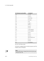
Страница 132: ...est program types or orientations cannot be separated Error in generating image E30 30 F 1 Image buffer overflow only for evaluation mode fixed frame rate Errors in test programs or system parameters E40 40 F Test program cannot be read found E41 41 F System parameter cannot be read interpreted E43 43 F Test program is not compatible with the firmware CP I O expansion errors E100 100 F 1 General C...

Страница 133: ...short circuit in output module E108 108 F 1 Overload short circuit in input module E109 109 F 1 Undervoltage output module E110 110 F 1 Undervoltage input module CPI module errors E150 150 F 1 Communicationerror EasyIP errors E200 200 F General EasyIP error E201 201 F EasyIP serverisn t running E202 202 F EasyIP communication error E203 203 W Invalid EasyIP request 1 Error can be configured Tab A ...

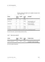
Страница 134: ...16 not used 4 uint16 not used 5 uint16 not used 6 uint16 not used 7 uint16 Test program preselection bit 0 R W 8 uint16 0 or 1 Accept preselected test program by Test program preselection bit 1 R W 9 uint16 0 or 1 test program by setting the accept i i l Test program preselection bit 2 R W 10 uint16 0 or 1 g p inputsignal Test program preselection bit 3 R W 11 uint16 0 or 1 Test program preselecti...

Страница 135: ...correctly oriented R 20 uint16 Warning corresponds to LED C red flashing R 22 uint16 Error status corresponds to LED C red R 23 uint16 Identified part type bit 0 R 24 uint16 Identified part type bit 1 R 25 uint16 Identified part type bit 2 R 26 uint16 Identified part type bit 3 R 27 uint16 Identified part type bit 4 R 28 uint16 Identified part type bit 5 R 29 uint16 Identified part type bit 6 R 30...

Страница 136: ...fterwards Tab A 6 Fast access to input and output registers A 6 4 Extended system status system information Name Read write FW Value type Comment Error code of the current error R 100 word 0 no error x error number see table section A 5 Error code of the current warning R 101 word 0 no error x error number see table section A 5 Device type R 102 word SBOI Q R1B 701 SBOC Q R1B 702 SBOI Q R1C 703 SB...

Страница 137: ...status system information A 6 5 Device system time Name Read write FW Value type Allowed values Comment Date year R W 150 uint16 2000 to 9999 The system time must be set again Date month R W 151 uint16 1 to 12 must be set again when the device is d i Date day R W 152 uint16 1 to 31 started again Time hours R W 153 uint16 0 to 23 Time minutes R W 154 uint16 0 to 59 Time seconds R W 155 uint16 0 to ...

Страница 138: ...203 uint16 0 to 20 Part type 4 R 204 uint16 0 to 20 Part type 5 R 205 uint16 0 to 20 Part type 6 R 206 uint16 0 to 20 Part type 7 R 207 uint16 0 to 20 Part type 8 R 208 uint16 0 to 20 Part type 9 R 209 uint16 0 to 20 Part type 10 R 210 uint16 0 to 20 Part type 11 R 211 uint16 0 to 20 Part type 12 R 212 uint16 0 to 20 Part type 13 R 213 uint16 0 to 20 Part type 14 R 214 uint16 0 to 20 Part type 15 ...

Страница 139: ...entationquality R 255 uint16 Orientationquality Used overall tolerance R 256 uint16 Used overall tolerance for testing the part Part no low word R 257 uint16 Low word of part no running no since device start for identification Part no high word R 258 uint16 Part no running no since device start for identification Date year of recording R 259 uint16 at trigger signal Date Month of recording R 260 u...

Страница 140: ...ture values is grouped into sections The sections begin at flagword 400 and are each offset by 100 Therefore section 1 of the feature values begins at 400 section 2 of the feature values begins at 500 etc The feature values are also saved as strings The addresses of the feature values begin at string 0 and are each offset by 5 Therefore the string of the 1st feature begins at 0 the string of the 2...

Страница 141: ...ature name R 460 char 32 Fixed feature name cut off if necessary Valid flag R 476 uint16 1 Feature could be calculated 0 Calculationfailed Feature type R 477 int16 Feature ID Deviation R 478 int16 Deviation 32000 Ū 32000 Good part 100 Ū 100 Feature value in front of the decimal R 479 uint16 Feature value as integer up to 32767 Feature value after the decimal R 480 uint16 Number of decimal places o...

Страница 142: ...y 107 Area x 2 108 Area y 2 109 Center of gravity x 110 Center of gravity y 111 Inertia x 112 Inertia y 113 Inertia xy 114 Degree of inertia axis 115 Pol min 116 Pol max 117 Circumference Tab A 12 ID of feature value The features available depend on the test program and on the firmware version of the device Note Further information is available from the service personnel of Festo AG Co KG ...

Страница 143: ...ff if necessary Feature name R 2 string Fixed feature name cut off if necessary not used R 3 string not used R 4 string 1 Example of addressing the 1st feature as from STR0 the 2nd Feature begins at STR5 Tab A 13 Features Results of the last test as string A 6 9 System parameters Name Read write Offset Value type Allowed values System parameters R W 7000 uint16 See dynamic help in the System param...

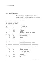
Страница 144: ...cate IP of camera and type in tabele THEN CFM 2 type interrogate IP in of tabele WITH V1 1 type 2 interrogate WITH V1 Index number in IP tabele WITH V192 IP adress WITH V168 IP adress WITH V2 IP adress WITH V10 IP adress IF FU32 first transfer V0 0 if successful THEN CMP 0 time Bap with T1 WITH V1000 delay time of 10s until camera has rebooted STEP loop Set trigger to camera logical 1 and send Eas...

Страница 145: ...ex number in IP tabelle WITH V1 Operand 1 M 2 E 3 A 4 R 5 TV 11 Str WITH V2 Number of wished operand 256 max WITH V400 No of first lokal Op for data WITH V400 No of first Operand in source CPU WITH V255 Adress of FW for status IF FU32 first transfer V0 0 if success THEN CMP 0 Time Bap with T1 WITH V100 1 Sec STEP Lesen Ganzzahl Word Easy Read THEN CFM 0 Read operands of controller WITH V1 Index nu...

Страница 146: ...A Technical appendix A 24 Festo P BE SBO Q EN en 0702a ...

Страница 147: ...Index B 1 Festo P BE SBO Q EN en 0702a Appendix B ...

Страница 148: ...B Index B 2 Festo P BE SBO Q EN en 0702a Contents B Index B 1 B 1 Index B 3 ...

Страница 149: ... 4 36 Activity LED C 5 4 Adapter kit 2 6 Aperture XIII 4 13 Assign IP address automatically 4 10 Auto MDI X XIII B Backlighting 1 18 Beginning of cycle 4 24 C C mount 1 13 Calculation time 4 16 Camera image 4 15 CAN interface 3 15 CE marking VII Certifications VII Characteristic XIV CheckKon XIII CheckOpti XIII 1 10 CMOS sensor XIII ...

Страница 150: ...address assignment Overview 4 45 CP modules XIII CP node XIII CP string XIII CP system XIII CP valve terminal XIV CPI modules XIV CPX modules XIV CPX terminal XIV CS mount 1 13 Cycle duration 4 22 D Depth of field XIV Depth of focus XIV Device as CPI module 4 42 DHCP server 4 10 Diagnosis 5 3 Digital input I XIV Digital output O XV Dimensions 2 5 Display and connecting elements 1 8 ...

Страница 151: ... controlled XIV Electrical connections 3 6 EMERGENCY STOP circuit 3 4 Error elimination 5 7 Ethernet XIV Ethernet address MAC ID A 4 Ethernet connection 3 12 Ethernet interface 3 11 3 13 Ethernet traffic LED B 5 4 Evaluation mode 4 17 Exposure time XIV 4 12 External lighting 1 17 Extraneous light 1 17 F Falling edge XIV Features 4 50 Fieldbus node XIV Fitting 2 3 Fixed focal depth 1 15 Fixed frame...

Страница 152: ...roller PLC 4 33 I I O expansion 4 38 I O modules XIV I Os XV Ignore trigger signal after ready for operation 4 19 Image optimisation 4 16 Image sharpness 4 13 Important user instructions X Input module XIV Inputs with signal function 4 34 Intended use VI Internal lighting 1 17 IP address A 4 L LEDs 5 3 Lens 1 13 2 7 Light source 1 17 ...

Страница 153: ...AC ID A 4 Main level 1 14 Mounting 2 6 4 12 Multicast 4 8 N Net classes A 5 Net mask A 5 Network settings 4 5 4 8 Networking and control 1 4 O Object distance 1 14 Operating voltage connection and I Os 3 8 Optics 4 12 Other inputs 4 34 Output duration 4 19 Output LED D 5 5 Output module XV Output time 4 19 P Pictograms XI ...

Страница 154: ...2 7 R Ready status LED A 5 3 Rising edge XV Rod light 1 18 S Safety information VIII Safety window 2 8 SBO DeviceManager 1 10 SBO DeviceManager XV 4 8 Search function 4 8 Sensor gain XV 4 12 Sensor size 1 14 Service IX Setting the aperture 4 13 Setting the focus 4 13 Siemens star A 7 Signal cables 3 4 Signal curve 4 21 4 26 4 30 Size of field of vision 1 14 Software packages 1 10 ...

Страница 155: ...rt lighting 4 19 Status display 5 3 Status controlled XV String allocation XV Supply lines 3 4 T Target group IX TCP IP XV Technical Data A 8 Test area 4 12 Test features 4 15 Test program XV 4 50 Text markings XI Trigger signal input 4 35 Triggered 4 17 4 18 V Variants of the Compact Vision System 1 5 1 6 Versions XII Viewing area 4 12 W Wide angle light 1 18 Work distance 1 14 ...

Страница 156: ...B Index B 10 Festo P BE SBO Q EN en 0702a Z Zoom 1 14 ...

Отзывы: