


Product variant
Code
Meaning
-PL
prepared for common supply manifold, vacuum and
exhaust port with QS push-in fittings inch (-BN-PL)
prepared for common supply manifold, vacuum port
with QS push-in fittings, exhaust port with open silencer
(-B-PO/-C-PO)
Pneumatic ports
-PO
prepared for common supply manifold, vacuum port
with QS push-in fittings inch, exhaust port with open
silencer (-BN-PO)
-ON
N/O, normally open (vacuum generation)
-OE
N/O, normally open (vacuum generation) with ejector
pulse
-OPE
N/O, normally open (vacuum generation) with power
ejector pulse (-C)
-CN
N/C, normally closed (no vacuum generation)
-CE
N/C, normally closed (no vacuum generation) with eject-
or pulse
Normal position of the
vacuum generator
-CPE
N/C, normally closed (no vacuum generation) with
power ejector pulse (-C)
Electrical connection
-N
M12 plug (5-pin)
Vacuum sensor
-
Without vacuum sensor (switching input PNP)
-1P
1 switching output PNP
-1N
1 switching output NPN
Tab. 3 Overview of variants
5.2
Function
5.2.1
Switching functions
The solenoid valve for vacuum generation switches as an N/C or N/O contact,
depending on the version, when pressurised with compressed air.
The switching output is configured as a N/O contact and switches depending on a
threshold value comparator
With air saving function activated the switching mode is set as the threshold value
comparator by switching output A.
Threshold value comparator
NO (N/O contact)
Tab. 4 Settings for switching points SP, hysteresis Hy and functional reserve FR
Switching behaviour
Product feature
Normally open contact (N/O)
-OE/-ON/-OPE
Normally closed contact (N/C)
-CE/-CN/-CPE
Tab. 5 Switching characteristics and product feature
Code
Switching output A
Switching input
-1P
Switching output positive switching pres-
sure sensor output A
Switching input positive switching
-1N
Switching output negative switching
pressure sensor output A
Switching input negative switching
without
vacuum
sensor
-
Switching input positive switching
Tab. 6 Switching output and switching input variants
Determination of switching point
The switching point (SP) is determined from the teach point (TP) and the function
reserve (35%).
SP = TP – 0.35*TP
The hysteresis has a fixed value.
5.2.2
Valve control
Control of the ejector pulse
–
Signal-controlled ejector pulse/power ejector pulse
The ejector pulse is generated via a control signal at the ejector pulse switch-
ing input. The duration of the ejector pulse can be set via the duration of the
control signal at the ejector pulse switching input. The vacuum solenoid valve
or the ejector pulse solenoid valve is controlled as defined by the input sig-
nal.
Destruction of the vacuum sensor due to overpressure (-CPE/-OPE)
The exhaust duct is sealed tightly during the power ejector pulse. This can cause
overpressure at the vacuum port and destroy the vacuum sensor.
•
Use power ejector pulse only in open vacuum systems.
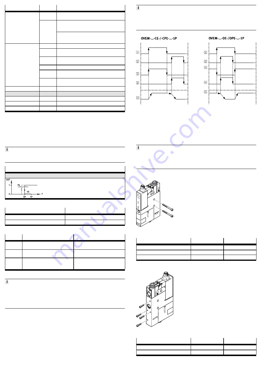
1
Control signal at the vacuum
switching input
2
Control signal at the switching
input ejector pulse / power eject-
or pulse
3
Switching position of vacuum
solenoid valve
4
Switching position of ejector
pulse solenoid valve
5
Vacuum port
Fig. 2 Valve control switching characteristics
6
Assembly
An unfavourable mounting position may impair the function of the product.
•
Avoid condensate accumulation in the device through a suitable mounting
position.
•
Exhaust air must be able to flow out unhindered.
Direct mounting
Fig. 3 Direct mounting on the side
Variant
Screws
Tightening torque
OVEM-...-05/-07/-10-...-B/-BN
M5
max. 2.5 Nm
OVEM-...-14/-20-...-B/-BN
M4
max. 2.5 Nm
OVEM-...-20/-30-...-C
M6
max. 2.5 Nm
Tab. 7 Size and tightening torque of the screws for direct mounting on the side
Fig. 4 Direct mounting on the back
Variant
Screw
Tightening torque
OVEM-...-05/-07/-10/-14/-20-...-B/-BN
M3
max. 0.8 Nm
OVEM-...-20/-30-...-C
M4
max. 0.8 Nm
Tab. 8 Size and tightening torque of the screws with direct mounting on the back


