Festo — EXPT-95/120 — 2021-08d
Assembly
13
4.3
Types of mounting
NOTICE
The removal of a motor results in a loss of homing on the corresponding axis. The axis must be homed
again during commissioning.
• Preferably choose mounting holes where the motor does not need to be removed.
4.3.1
Direct fastening
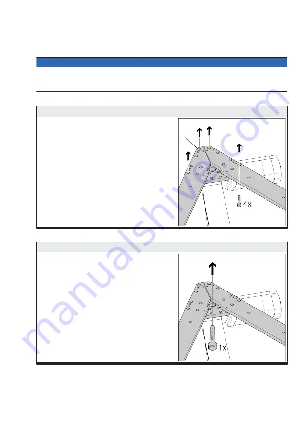
Direct fastening variant 1 with M8 screws in accordance with DIN 912
Direct fastening to the frame with at least 4 screws per
corner bracket.
Dimensions
The 4 screws should be as far apart as possible to
ensure a torsionally rigid connection.
If the slotted holes
1
are used, the bearing surface
of the screws is too small. Use the accompanying
washers.
1
Tab. 7: Direct fastening variant 1
Direct fastening variant 2 with M20 screws in accordance with DIN 912
Direct fastening to the frame with one screw per corner
bracket.
There is a central hole for this purpose at every
bracket.
–
Make sure that the bearing surface lies in the area
of the corner brackets.
Tab. 8: Direct fastening variant 2


