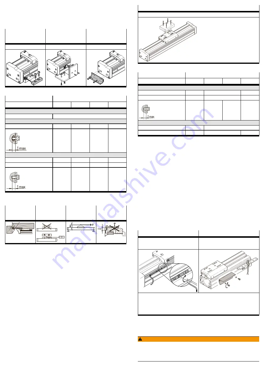
3. Tighten retaining screws.
Observe max. tightening torque and max. screwin depth.
In the case of planar and 3dimensional gantries, pay attention to parallelism,
product height and alignment of the axes.
For additional information, contact your local Festo Service.
Profile mounting MUE
(EGC-...-...M)
Slot nut NST For mount-
ing slot
(EGC-...-...Y)
Foot mounting HPE
(EGC-...-F)
Mounting via profile groove
Mounting via profile groove
Mounting via thread
Tab. 1 Overview of mounting components
EGC-FA
Size
70
80
120
185
Profile mounting MUE
Screw
Instruction manual
è
Slot nut NST
Screw (side/bottom)
M5
M5
M6
M6
max. screwin depth t
max
[mm]
6
6
12
12
Foot mounting HPE
Screw
M5
M5
M8
M10
max. tightening torque
[Nm]
5.9
5.9
24
47
max. screwin depth t
max
[mm]
10
10
16
20
Tab. 2 Information on mounting attachments
7.4
Mounting the attachment component
Collision-free
Flat
Centre of gravity
and tilting
moment
Max. screw-in
depth
Tab. 3 Requirements for attachment component
Requirement
–
No collision in the movement space of the attachment component with
mounting and sensor components.
–
Flatness of the mounting surface of the attachment component of 0.01 mm
above the slide surface.
–
Position of the centre of gravity and tilting moment (force F parallel to the axis
of motion) of the attachment component centrally on the slide and close to
the slide surface (short lever arm a).
–
The maximum screwin depth of the retaining screws is not exceeded.
1. Select accessories
è
2. Place centring components in centring holes.
3. Position the attachment component on the slide.
4. Tighten retaining screws.
Observe max. tightening torque and max. screwin depth.
When using an additional external guide, ensure exact parallelism and alignment
of the axes and guide.
Recommendation: use guide fixings with tolerance compensation.
Direct mounting
Mounting via thread
Tab. 4 Overview of attachment component
EGC-FA
Size
70
80
120
185
Direct mounting
Screw (side/top)
M5
M5; M6
M6; M8
Max. tightening torque
[Nm]
5.9
5.9; 9.9
9.9; 24
Max. screwin depth t
max
[mm]
8.4
9.5
10
15
Centring (bore tolerance H7)
Centring pins (side/top)
[mm]
Æ
5
–
Centring sleeve (side/top)
[mm]
–
Æ
7/
Æ
9
Æ
9
Tab. 5 Information on attachment component
7.5
Mounting accessories
Requirement
–
No collision in the movement space of the attachment component with
mounting and sensor components.
–
Protection against uncontrolled overtravel of the end positions.
–
Homing to reference switch or end position.
–
Query of end positions or intermediate positions.
–
Avoidance of hard impacts at the end positions.
–
Prevention of contamination in the slots.
1. Select accessories
è
2. Mount mechanical end position protection:
–
Mount shock absorber retainer.
–
Mount shock absorber or emergency buffer.
3. Mount the sensor (reference or query):
–
Mount the sensor bracket and switch lug (depending on the type of
mounting).
–
Mount the sensor.
–
Fasten the cable with clips.
4. Mount the slot cover.
Instruction manuals
è
Profile groove
Sensor bracket
–
Switch lug: mounting on slide
–
Sensor: mounting via profile groove
–
Switch lug: mounting on slide
–
Sensor bracket: mounting via profile groove
–
Sensor: mounting on the sensor bracket
–
Protect the sensor from external magnetic or ferritic influences (e.g. min. 10 mm distance to
slot nuts).
–
Preferably use hardware limit switches with normally closed function (protection guaranteed
even in case of sensor failure).
–
Query switching lug only with inductive sensor.
Instruction manual
è
Tab. 6 Overview of Sensor Mountings
8
Commissioning
8.1
Safety
WARNING!
Risk of injury due to unexpected movement of components.
•
Protect the positioning range from unwanted intervention.
•
Keep foreign objects out of the positioning range.
•
Perform commissioning with low dynamic response.


