9
Operation
Warning
Uncontrolled fast moving parts can cause injury to people in the vicinity of the
DFPI.
· Make sure that:
no−one can reach into the operating direction of the moving components
(e.g. use a protective grid)
there are no objects within the positioning path.
It should not be possible to touch the DFPI until the mass has come to a
complete stand.
10
Care and maintenance
If used as designated in the operating instructions, the device will be free of
maintenance.
11
Dismantling and repairs
Make sure that the following sources of energy are switched off:
electrical power supply
the compressed air supply
1. Remove the slide plate from the piston rod.
2. Remove the screws on the flange of the processing valve or penstock shut−off
valve.
3. Remove the drive (if necessary including mounting adapter and coupling
extension).
Recommendation: Return the product to our repair service for overhaul.
This ensures that the necessary fine adjustments and checks will be given
particular attention.
Information about spare parts and auxiliary means
è
www.festo.com/spareparts.
12
Troubleshooting
Fault
Possible cause
Remedy
Piston rod does not move in
the desired direction
Compressed air tubes
interchanged
Correct the tubing
the desired direction
Displacement encoder cable
incorrectly connected on
positioning controller or on
DFPI (e.g. connections on pin 1
and pin 3 interchanged).
Correct the connection
Fig.11
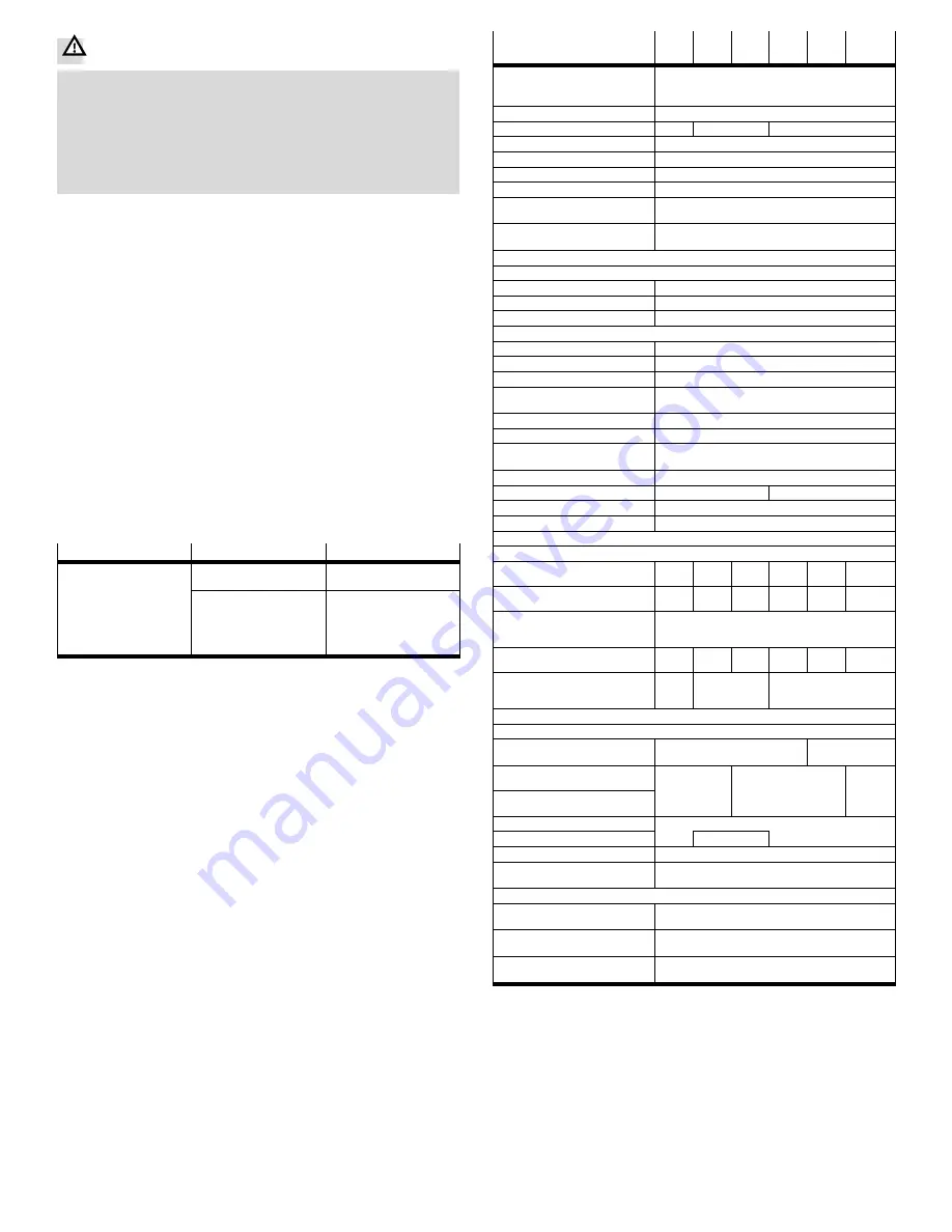
13
Technical specifications
DFPI−...−...−ND2P−E−P
−100−
Ū
−125−
Ū
−160−
Ū
−200−
Ū
−250−
Ū
−320−
Ū
Based on standard
(connection to valves and
fittings)
DIN 3358
Type of mounting
On flange to DIN 3358
Flange hole pattern
F07
F10
F10, F14
Constructional design
Piston rod, cylinder barrel
Cushioning
None
Assembly position
As desired
Method of operation
Double−acting
Position sensing
For position switched integrated with displacement
encoder
Measuring principle of
displacement encoder
Potentiometer
Resistance value of displacement encoder (on the T.E.P.) as a function of the stroke length
1)
˚
290 mm
[k]
5
,
290 mm to 590 mm
[k]
10
,
590 mm to 990 mm
[k]
20
Pneumatic connection
Standard O.D. for tube outer
∅
8 mm
Operating pressure
[bar]
3
Ū
8
Nominal operating pressure
[bar]
6
Operating medium
Filtered compressed air, grade of filtration 40 m,
lubricated or unlubricated
Max. operating voltage DC
[V DC]
15
Max. line length
[m]
30
Protection class
IP65, IP67 in assembled state to IEC60529;
IP69K, NEMA 4 in assembled state
Stroke
[mm]
40
Ū
990
Stroke reserve
[mm]
3
4
Ambient temperature
[°C]
20
Ū
+60
Outdoor use
C1 use in weather−protected areas
Product weight
Basic weight
with 0 mm stroke
[g]
3476
5530
6529
13 946
22 569
35 359
Additional weight
per 10mmstroke
[g]
80
145
159
187
325
399
Additional weight
of displacement encoder
per 10 mm
[g]
2
Moving load
with 0 mm stroke
[g]
1228
1944
2250
4722
7059
11417
Additional weight
of moving load per
10 mm stroke
[g]
27
52
87
Material
Cylinder barrel
Wrought aluminium alloy,
anodised
High−alloy,
stainless steel
Cap (end cap)
Wrought
aluminium alloy,
Die−cast aluminium,
painted
Wrought
aluminium
Bottom cap (bearing cap)
aluminium alloy,
anodised
painted
aluminium
alloy,
anodised
Piston rod
High−alloy stainless steel
Screws
Steel
Seals
Nitrile rubber
2)
Note on materials
Contains paint wetting impairment substances,
conforms to RoHS
Vibration resistance
to DIN/IEC 68 parts 2−6
Tested to severity level 2
Continuous shock resistance
to DIN/IEC 68 parts 2−82
Tested to severity level 2
CE mark (see declaration of
conformity
è
www.festo.com)
To EU EMC directive
1)
T.E.P. = theoretical electrical path
2)
For piston diameter 100 mm
also thermoplastic polyurethane elastomer
Fig.12


