


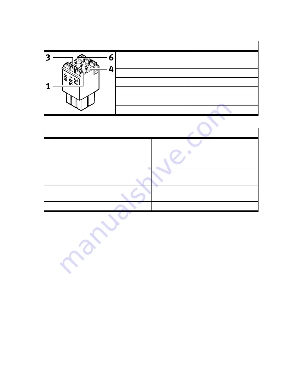
Requirements for the counterplug
Design
DFMC 1.5/ 3-ST-3.5 from
Phoenix Contact or compatible
Signal contacts
6 (3-pin, 2-row)
Nominal current
8 A
Rated voltage (III/2)
160 V
Grid dimension
3.5 mm
Strip length
10 mm
Tab. 60 Requirements for the counterplug
Requirements for the connecting cable
Design
–
2 wires for the line to the holding brake, twis-
ted in pairs, separately shielded
–
2 wires for the line to the temperature
sensor, twisted in pairs, separately shielded
Min. conductor cross section including cable end
sleeve with plastic sleeve
0.25 mm
2
Max. conductor cross section including cable end
sleeve with plastic sleeve
0.75 mm
2
Max. length
50 m
Tab. 61 Requirements for the connecting cable
Requirement for the temperature sensor in the motor
–
Electrically safe separation from the motor phases in accordance with IEC 61800-5-1, voltage
class C, overvoltage category III.
Requirements for the shield support
–
Make unshielded cable ends as short as possible (max. 150 mm).
–
Put in place both sides of the cable shield.
8.9.3
Shield support of the motor cable
Requirements for the device-side shield support of the motor cable
The type of shield support depends on the design of the motor cable. If, for example, a hybrid cable is
used to connect the motor, holding brake, and temperature sensor, the following options exist for pla-
cing the shield on the device side:
Option 1: All motor cable shields are connected over a large surface with a shield sleeve at the cable
end and placed below the shield clamp on the front side of the CMMT-AS.
Installation
63
Festo — CMMT-AS-C2/C4-3A-... — 2018-02


