CAMC−D−8E8A
Festo AG & Co. KG
Postfach
D−73726 Esslingen
++49/711/347−0
www.festo.com
(en) Operating instructions
749 891
0910NH
Original: de
Note
Installation and commissioning may only be carried out by qualified personnel
with knowledge of and experience with electrical control technology.
1
2
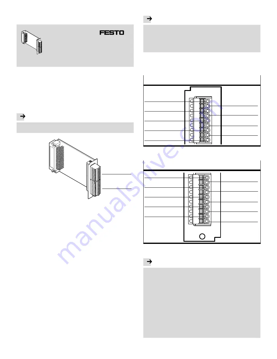
Fig.1: Control sections and connections
1
Function and application
The interface CAMC−D−8E8A serves to expand the digital IOs in CMMD and CMMP
motor controllers. For the CMMP−AS, up to two CAMC−D−8E8A interfaces are
supported simultaneously.
Up to 8 digital I/O modules can be allocated predefined functions with this
interface. Further, 8 digital 24 V inputs are also available.
The CAMC−D−8E8A interface has the following performance characteristics:
digital 24 V inputs
1
individually switchable digital I/O modules
2
with 100 mA power rating each
plug connectors from PHOENIX Contact MicroCombicon
Inputs and outputs are electrically isolated through the optocoupler
Inputs and outputs have short−circuit and overload protection
The interface CAMC−D−8E8A is intended for installation in the CMMD and CMMP
motor controllers.
2
Requirements for product use
· Compare the limit values specified in these operating instructions with those of
your application (e.g. electrical data, temperatures). Only compliance with the
load limits allows operation of the product in compliance with the relevant
safety regulations.
· Comply with the regulations of the trade association, the German Technical
Control Board (TÜV) or relevant national regulations.
· Use the product in its original condition without any unauthorised
modifications.
· Note the warnings and instructions on the product and in the relevant operating
documentation.
3
Electrical installation
3.1 Power supply
Note
The permissible input voltage range in operation is 15...32VDC.
The power supply to the digital outputs on the CAMC−D−8E8A interface is
provided by a supplemental power supply to be connected externally. The
nominal input voltage for the I/O power supply is 24VDC.
Even when the digital inputs are used, the reference potential GND 24 V of the
24VDC power supply must be connected to the CAMC−D−8E8A interface.
3.2 Pin allocation
The following components can be found on the front plate of the CAMC−D−8E8A
interface:
1
Connector [X21] for 8 digital inputs:
1)
PHOENIX MicroCombicon MC 0.5/9−G−2.5 (9−pin)
DIN_Ext1.6
DIN_Ext1.7
DIN_Ext1.5
DIN_Ext1.3
DIN_Ext1.1
GND24V
DIN_Ext1.4
DIN_Ext1.2
DIN_Ext1.0
1)
Counterplug: Connector [X21] for 8 digital inputs: PHOENIX MicroCombicon FK−MC 0.5/9−ST−2.5
Fig.2
2
Connector [X22] for 8 digital I/O modules:
2)
PHOENIX MicroCombicon MC 0.5/10−G−2.5 (10−pin)
DOUT_Ext1.7
+24VDCexternal
DOUT_Ext1.6
DOUT_Ext1.4
DOUT_Ext1.2
DOUT_Ext1.0
DOUT_Ext1.5
DOUT_Ext1.3
DOUT_Ext1.1
GND24V
2)
Counterplug: Connector [X22] for 8 digital I/O modules: PHOENIX MicroCombicon FK−MC 0.5/10−ST−2.5
Fig.3
Note
The MicroCombicon from PHOENIX Contact counterplugs for [X21]
(FK−MC 0.5/9−ST−2.5) and [X22] (FK−MC 0.5/10−ST−2.5) are supplied together
with the CAMC−D−8E8A interface.
The lines are wired using crimp connections. To make these connections, the
cable is stripped approx. 8mm and then inserted into the corresponding orifice.
Press the orange crimp lock downward with an appropriate screwdriver,
ballpoint pen or the like.
When the lock is released, the line is locked in place. The maximum permissible
cable cross section is 0.5mm
2
or AWG20.
If the CAMC−D−8E8A interface is also supposed to control digital outputs, an
additional external 24 V supply voltage must be applied to [X22].
Since the GND24 V and +24 VDClines have to transmit the entire current for all
connected outputs, they must be designed accordingly in their cable cross
section (AWG20 recommended).


