background image

27 / 55

Festo 7DFPIb_en

4.4 

Repair steps for the piston

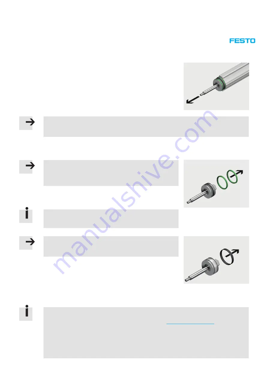
1. Carefully pull the piston rod out of the cylinder barrel.
2. Inspect the cylinder barrel and piston rod for damage.

Note

If the cylinder barrel is showing signs of significant damage (especially scoring on the bearing surface), the seals of 

the piston can no longer provide a clean seal and the entire linear actuator must be replaced. 

4.4.1 

Replacing the piston components

Note

The lip rings must not, under any circumstances, be levered out of the 

groove using a sharp-edged object as this can damage them. Use a flat, 

blunt object.

1. Carefully remove the lip rings from the seats in the piston.
2. Inspect the lip rings for damage.

Scores in the lip seals cause leaks between the lip ring and the cylinder 
barrel bearing surface. Damage to the sliding seal has a negative effect on 
the sliding characteristics of the piston.

Note

Do not, under any circumstances, bend the sliding ring open too far, as this 
can damage it. 

3.

Slightly

 open the sliding ring at the transverse groove and remove from the

piston in the direction of the axis.

4.4.2 

Replacing the magnet holder

If the magnetic driver (magnet) of the displacement encoder is damaged, together with the corresponding holder or 
the displacement encoder (linear potentiometer) that is still in the cylinder barrel, these can only be replaced using a 
spare parts kit. Further information can be found on the Festo website (

http://spareparts.festo.com

).

In this case, the magnet holder must be removed from the piston rod.
The spare parts kit contains:
– The magnet
– The magnet holder with O-ring and retaining ring
– The magnet rod with cable connector, all electrical cables and the plug

Содержание 1548004

Страница 1: ...Repair instructions en Linear actuator DFPI ND2P 7DFPIb_en...

Страница 2: ...reproduction distribution or sale of this document or communication of its contents to others without express authorisation is prohibited Offenders will be held liable for damages All rights reserved...

Страница 3: ...ns into consideration if necessary These repair instructions have been prepared with care Festo AG Co KG does not however accept liability for any errors in these repair instructions or their conseque...

Страница 4: ...P A 19 3 6 DFPI 200 250 320 ND2P G2 21 4 Repair steps 23 4 1 Preparation for dismantling 23 4 1 1 Disconnecting supply lines from the linear actuator 24 4 2 Visual inspection 24 4 3 Repair steps for...

Страница 5: ...ting 49 5 1 DFPI ND2P C1V A 49 5 2 DFPI ND2P G2 52 6 Cleaning and greasing 53 6 1 Cleaning 53 6 2 Greasing 53 6 2 1 Definition of terms 53 7 Maintenance and care 54 8 Tools 54 8 1 Standard tools 54 8...

Страница 6: ...tion This can be found in the online spare parts catalogue on the Festo website http spareparts festo com Assembly aids Contains an overview of available assembly aids such as lubricating greases thre...

Страница 7: ...d therefore not permitted Repairs must only be carried out in conjunction with these repair instructions as well as the respective operating instructions for the device Instead of carrying out the rep...

Страница 8: ...n the Technical data sections of the accompanying documentation 2 General product description 2 1 Functional description The DFPI ND2P is a linear actuator with the functional principle of a double ac...

Страница 9: ...48041 1548044 A complete overview of features accessories type codes technical data and dimensions for the linear actuator DFPI ND2P can be found in the product catalogue or on the Festo website www f...

Страница 10: ...signal E External controller attachment position no specification indicates internal attachment position G2 Second generation E Retracted piston safety position no specification indicates advanced saf...

Страница 11: ...6 8 9 10 11 12 13 14 10 11 15 16 17 18 19 8 20 1 2 26 27 7 7 21 22 23 24 25 This diagram is intended only to provide an overview of the individual components To order spare and wearing parts please us...

Страница 12: ...5 0057 5 B ARA 32 0075 0 B ARA 32 0073 5 B 10 Piston 11 Lip seal 100 88 8 5 75FKM181327 125 110 10 160 145 10 E4 12 Sliding ring 13 Magnetic strip 14 O ring I 3601 B 20 2 N NBR70 I 3601 B 20 2 N NBR70...

Страница 13: ...12 13 14 10 11 15 16 17 18 19 8 20 1 2 29 30 7 7 21 22 23 24 25 27 28 26 This diagram is intended only to provide an overview of the individual components To order spare and wearing parts please use t...

Страница 14: ...5 75FKM181327 125 110 10 160 145 10 E4 14 O ring I 3601 B 20 2 N NBR70 I 3601 B 20 2 N NBR70 I 3601 B 25 2 5 N NBR70 15 Magnet holder 16 O ring I 3601 B 27 2 5 N NBR75 I 3601 B 27 2 5 N NBR75 I 3601...

Страница 15: ...1 12 13 14 10 11 15 16 17 18 19 1 2 7 8 20 27 28 21 22 23 24 25 26 This diagram is intended only to provide an overview of the individual components To order spare and wearing parts please use the onl...

Страница 16: ...I 3601 B 152 4 N NBR75 9 Piston rod ARA 25 0057 5 B ARA 32 0075 0 B ARA 32 0073 5 B 10 Piston 11 Lip seal 100 88 8 5 75FKM181327 125 110 10 160 145 10 E4 12 Sliding ring 13 Magnetic strip 14 O ring I...

Страница 17: ...16 17 18 19 21 22 23 24 25 26 27 28 29 1 30 31 32 33 34 35 36 6 9 10 20 11 This diagram is intended only to provide an overview of the individual components To order spare and wearing parts please us...

Страница 18: ...pacer disc 18 Washer 19 Magnet holder 20 Shim DIN 988 22 32 0 2 DIN 988 22 32 0 2 DIN 988 22 32 0 2 21 O ring I 3601 B 25 2 5 N NBR75 I 3601 B 25 2 5 N NBR75 I 3601 B 25 2 5 N NBR75 22 Magnet 23 Retai...

Страница 19: ...15 12 16 17 18 21 22 23 20 19 24 25 29 1 37 26 27 28 38 39 6 31 33 32 35 36 34 30 This diagram is intended only to provide an overview of the individual components To order spare and wearing parts pl...

Страница 20: ...A4 70 17 Spacer disc 18 Washer 19 Magnet holder 20 Shim DIN 988 22 32 0 2 DIN 988 22 32 0 2 DIN 988 22 32 0 2 21 O ring I 3601 B 25 2 5 N NBR75 I 3601 B 25 2 5 N NBR75 I 3601 B 25 2 5 N NBR75 22 Magn...

Страница 21: ...2 16 17 19 20 21 22 23 24 25 26 27 1 34 35 6 9 10 18 11 28 29 30 31 32 33 This diagram is intended only to provide an overview of the individual components To order spare and wearing parts please use...

Страница 22: ...7 2 5 N NBR70 16 Washer 17 Magnet holder 18 Shim DIN 988 22 32 0 2 DIN 988 22 32 0 2 DIN 988 22 32 0 2 19 O ring I 3601 B 25 2 5 N NBR75 I 3601 B 25 2 5 N NBR75 I 3601 B 25 2 5 N NBR75 20 Magnet 21 Re...

Страница 23: ...ase of an error e g defective valve block The linear actuator may then advance unexpectedly during dismantling thus crushing body parts Switch off the power supply in the following order to allow the...

Страница 24: ...be unplugged when removing the housing from the end cap 3 Unscrew the retaining screws from the two plug halves 4 Separate the two plug halves 4 2 Visual inspection Check the linear actuator for visi...

Страница 25: ...in the bearing and end caps are free from defects 3 Unscrew the two push in L fittings from the bearing and end caps 4 Remove the front cap nuts from the tie rods 5 Remove the tie rods from the beari...

Страница 26: ...rod seal 3 see section 6 1 Cleaning 1 3 2 6 Grease the rod seal as follows Area Greasing 1 Grease reservoir1 for piston rod Fill 2 3 with grease 2 External surface for bearing cap Apply a thin film 3...

Страница 27: ...ng and the cylinder barrel bearing surface Damage to the sliding seal has a negative effect on the sliding characteristics of the piston Note Do not under any circumstances bend the sliding ring open...

Страница 28: ...e piston rod together with the magnetic strip Assembling the piston 1 Place one piston half on the piston rod The marking on the magnetic strip must face away from the magnet holder i e towards the be...

Страница 29: ...must be greased as follows before mounting Area Greasing 1 and 4 Grease reservoir1 facing away from sliding ring Fill 2 3 with grease 2 and 3 External surface for the bearing surface of the cylinder...

Страница 30: ...cylinder barrel 2 Carefully pull the end cap module out of the cylinder barrel 3 Clean the cylinder barrel with a soft cloth see section 6 1 Cleaning 4 Remove the two O rings from the seats of the end...

Страница 31: ...the end cap module 4 5 1 Replacing the displacement encoder This section can be skipped if the displacement encoder linear potentiometer is not faulty and does not need to be replaced Note Be careful...

Страница 32: ...5 2 Replacing the controller with electronic function module Note The controller and electronic function module contain electrostatically sensitive components Electrostatic discharges caused by impro...

Страница 33: ...the electronic function module The following repair steps can be skipped if the electronic function module does not need to be replaced Removing the electronic function module Note When removing the t...

Страница 34: ...que of 0 5 Nm 10 4 Plug in the bottom plug connector The colours of the individual wires in the cable harness are as follows from top to bottom end cap facing downwards Brown White Blue Black Grey 5 P...

Страница 35: ...ews to a tightening torque of 0 8 Nm 4 Plug the valve cable assembly into the valve block in accordance with the labels Y1 Y2 Y3 and Y4 4 5 4 Replacing the valve block The valve block controller and e...

Страница 36: ...e that these are not lost when removing the valve block If the pneumatic tubing is damaged they will also need to be replaced The lengths and diameters can be found in the table Length and diameter of...

Страница 37: ...the chamfers are facing outwards 8 Screw in the mounting screws to a tightening torque of 1 4 Nm 9 Plug the valve cable assembly into the valve block so that the pilot line numbers correspond with the...

Страница 38: ...unting screws in the intermediate cap and tighten to the appropriate torque Type Tightening torque DFPI 100 ND2P 1 2 Nm 10 DFPI 125 ND2P 1 2 Nm 10 DFPI 160 ND2P 1 2 Nm 10 DFPI 200 ND2P 3 0 Nm 10 DFPI...

Страница 39: ...ing the end cap Do not under any circumstances lever the end cap off the cylinder barrel using a sharp edged object as this could damage the O ring or cylinder barrel 2 Carefully pull the end cap out...

Страница 40: ...iver and input boards are not faulty and do not need to be replaced Removing the driver board with the input board Note The driver and input boards contain electrostatically sensitive components Elect...

Страница 41: ...5 Pull the customer plug assembly out of the input board To do this push a screwdriver into the recesses behind the lines and use it to lever out the lines Installing the driver board with the input...

Страница 42: ...block and controller make up the control unit of the linear actuator The four individual valves together with the valve base form a single unit and move the linear actuator to the required travel pos...

Страница 43: ...o be replaced The lengths and diameters can be found in the table Length and diameter of pneumatic tubing Type Tubing diameter in mm Length in mm for pilot line 2 Length in mm for pilot line 4 DFPI 10...

Страница 44: ...3 and Y4 Y4 Y3 Y2 Y1 10 Plug the pneumatic tubing from pilot port 2 on the valve block into the push in connector on the end cap When doing so thread the pneumatic tubing through the input board in an...

Страница 45: ...2P 3 0 Nm 10 DFPI 320 ND2P 3 0 Nm 10 4 Plug the pneumatic tubing from pilot port 4 on the valve block into the push in connector on the intermediate cap Thread the pneumatic tubing through the control...

Страница 46: ...the piston is sitting fully in the cylinder barrel 5 Apply a light coating of grease to the O ring of the bearing cap Caution There is a danger of crushing when pressing in the bearing cap Make sure t...

Страница 47: ...the displacement encoder into the longitudinal hole of the piston and place the end cap on the cylinder barrel so that it is in full contact with the cylinder barrel Sizes DFPI 200 250 320 1 Push the...

Страница 48: ...ting supply lines to the linear actuator Unprotected variant 1 Push the two plug halves of the displacement encoder together 2 Tighten the retaining screws on the two plug halves to a torque of 0 5 Nm...

Страница 49: ...g the valve block Piston rod jamming due to high transverse forces Reduce transverse forces Piston rod not moving following successful initialisation Initialisation Problem with electrical connection...

Страница 50: ...ng voltage outside permissible range Check operating voltage Check contacts of electrical cables for mains voltage Check voltage between pin 1 and pin 3 Excessive voltage will damage the positioner In...

Страница 51: ...e are no transverse forces acting on the piston rod Normal operation Dirt in valve block Replace valve block see section 4 5 4 Replacing the valve block Replace valve block see section 4 7 3 Replacing...

Страница 52: ...steps for the end cap module 4 7 Repair steps for the end cap module Problem with 3 pin plug connection to displacement encoder Check electrical connection of 3 pin plug Dismantle 3 pin plug see sect...

Страница 53: ...ication the piston rod with assembled piston and piston seals must be moved across the entire stroke of the cylinder barrel several times after greasing in order to produce an even lubricant film Grea...

Страница 54: ...andard tools among others are required to repair the linear actuator Screwdriver Wrench Flat pliers Torque spanner 8 2 Equipment and measuring devices The reference for all equipment and measuring dev...

Страница 55: ...developed with regard to hardware and software The hardware status and where applicable the software status of the product can be found on the rating plate of the product If the Electronic Documentati...

Отзывы: