


Supplied By www.heating spares.co Tel. 0161 620 6677
6
Tempra 12 / 18
Before calling the service centre, check that the problem is not due to no gas or mains
power supply.
Table 2
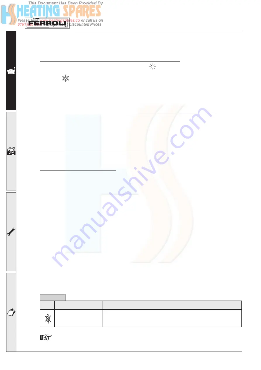
Boiler locked-out
LED
Problem
Solution
Check if the gas isolation valve upstream of the boiler and on the counter are open.
Turn knob “A” Fig. 1 to “Reset” and then release it.
In the event of repeated boiler lock-out, contact the nearest service centre.
1.4 Settings
Summer/Winter setting and system temperature control
With knob
“B”
Fig. 1 in the position of the symbol
(Summer), the central heating function is
deactivated. This is only for use with optional water control kit. With the knob
“B”
Fig. 1 in the position of
the symbol
(Winter), both the central heating function and domestic hot water are active, if used with
an external clock/programmer knob “B” must be kept in the winter position and the clock/programmer
used to control the central heating and hot water. Turning the knob clockwise increases the central heating
water temperature, anticlockwise decreases it. The temperature can be set from a minimum of 35° to a
maximum of 85°. It is not recommended, however, to operate the boiler below 45°.
Setting the ambient temperature (using the optional room thermostat)
Set, using the room thermostat or remote control, the temperature required inside the rooms. Based
on the command from the room thermostat, the boiler is ignited and heats the system water to the set
central heating outlet temperature. When the required temperature inside the rooms is reached, the
boiler switches off. If no room thermostat or remote control is available, the boiler will maintain the
system at the set central heating outlet temperature.
Domestic hot water temperature control
Set the hot water cylinder temperature, using knob “D” (supplied in the optional kit).
System water pressure control
Manually filling the central heating system with external connection and cock. The filling pressure when
the system is cold, as read on the boiler water pressure gauge, must be around 1.0 bar (at least 0.5
bar). If the pressure drops during operation to a value lower than the minimum described above, the
User must restore the initial value using the filling loop. Once the operation is completed, always close
the filling loop. This device is fitted to the system by the installer.
1.5 Maintenance
It is recommended to have annual service of the appliance performed by qualified personnel. Please
refer to Chap. 3.3 in this manual for further information.
The casing, the control panel and the aesthetic parts of the boiler can be cleaned using a soft and damp
cloth, dipped in soapy water if necessary. Do not use abrasive detergents or solvents.
1.6 Troubleshooting
Any anomalies or operating faults are signalled by the LEDs on the control panel. The following table lists
the faults that may arise due to simple problems that can be resolved by the user.


