


SUN P7
10
EN
cod. 3540I811 - 04/2011 (Rev. 00)
Weekly programme modification
1.
Press the Programming button "P" (detail 5 - fig. 1)
2.
Select the day to be programmed with the + and - buttons (details 4 and 6 - fig. 1):
•
Day 1 and Radiator flash: Monday heating programming
•
Day 2 and Radiator flash: Tuesday heating programming
•
Day 3 and Radiator flash: Wednesday heating programming
•
Day 4 and Radiator flash: Thursday heating programming
•
Day 5 and Radiator flash: Friday heating programming
•
Day 6 and Radiator flash: Saturday heating programming
•
Day 7 and Radiator flash: Sunday heating programming
•
Day 15 and Radiator flash: heating programming period Monday - Friday
•
Day 67 and Radiator flash: heating programming period Saturday - Sunday
•
Day 16 and Radiator flash: heating programming period Monday - Saturday
•
Day 17 and Radiator flash: heating programming period Monday - Sunday
•
Day 17 and Radiator flash: not used
3.
Press the Programming button "P" (detail 5 - fig. 1):
4.
06:30 and Radiator flash, ON, 1
•
Use the + and - buttons (details 4 and 6 fig. 1) to modify the start of the 1st ON
time band; example 06:00 Press the Programming button "P" (detail 5 - fig. 1)
5.
08:30 and Radiator flash, 2
•
Use the + and - buttons (details 4 and 6 fig. 1) to modify the start of the 1st OFF
time band; example 09:00 Press the Programming button "P" (detail 5 - fig. 1)
6.
12:00 and Radiator flash, ON, 3
•
Use the + and - buttons (details 4 and 6 fig. 1) to modify the start of the 2nd ON
time band; example 12:30 Press the Programming button "P" (detail 5 - fig. 1)
7.
12:00 and Radiator flash, 4
•
Use the + and - buttons (details 4 and 6 fig. 1) to modify the start of the 2nd OFF
time band; example 14:00 Press the Programming button "P" (detail 5 - fig. 1)
8.
16:30 and Radiator flash, ON, 5
•
Use the + and - buttons (details 4 and 6 fig. 1) to modify the start of the 3rd ON
time band; example 16:00 Press the Programming button "P" (detail 5 - fig. 1)
9.
22:30 and Radiator flash, 6
•
Use the + and - buttons (details 4 and 6 fig. 1) to modify the start of the 3rd OFF
time band; example 23:30 Press the Programming button "P" (detail 5 - fig. 1)
10. By repeating the above procedure it is possible to programme the 4th ON time band
and the 4th OFF time band.
11. Press the Programming button "P" (detail 5 - fig. 1) for 3 seconds to exit the pro-
gramming mode.
Parameters menu
Press the programming button “M” (detail 2 - fig. 1) for 5 seconds to access the param-
eters menu. The parameter "u01" is displayed: identified by the message SET 01. Press
the button “P” (detail 5 - fig. 1) to scroll the list of parameters.
To modify the value of a parameter just press the + and - buttons (details 4 and 6 - fig. 1):
the change will be automatically saved. After modifying the parameter, it is necessary to
wait 3 seconds: the data flashes and is stored.
Table. 1
Press the "operation mode selection - M" button (detail 2 – fig. 1) for 5 seconds to exit
the menu.
Service parameters Menu
Press the programming button
“P”
(detail 5 - fig. 1) for 10 seconds to access the param-
eters menu. The parameter "t01" is displayed: identified by the message SET 01. Press
the button “P” (detail 5 - fig. 1) to scroll the list of parameters.
To modify the value of a parameter just press the + and - buttons (details 4 and 6 – fig. 1):
the change will be automatically saved. After modifying the parameter, it is necessary to
wait 3 seconds: the data flashes and is stored.
Table. 2
Press the programming button
“P”
(detail 5 - fig. 1) for 10 seconds to exit the menu.
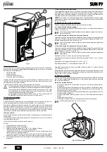
2.5 Operating instructions
Once the burner is installed and correctly adjusted, its operation is fully automatic without
requiring any control by the user. In case of faults or no fuel, the burner stops and shuts
down. It is advisable to fill with fuel before it completely finishes, to avoid irregular burner
operation.
Make sure the room where the burner is installed is free of flammable materials or ob-
jects, corrosive gases and volatile substances, and that it is not dusty. In fact, dust drawn
by the fan sticks to the blades and reduces the air flow or obstructs the flame stability
disk, affecting its efficiency.
B
Do not let unskilled persons or children tamper with the burner.
Max. power adjustment (parameter u02) depending on the boiler
Parameters
Description
Range
Default
u01
Delivery setpoint adjustment
30 - 80°C
80°C
u02
Burner max. power
1 - 5
5
u03
Burner operation methods (see par. 3.1)
0 - 2
0
Parameters Description
Range
Default
t01
Pellet loading function
0=Disabled 1=Ena-
bled
0=Disabled
t02
Delivery probe
0=Disabled 1=Ena-
bled
1=Enabled
t03
Fan setpoint in Lighting
0-200 Pa
51 Pa
t04
Auger activation time in Lighting
0-100 (1=4 sec-
onds)
12
t05
Adjustment calculation Timer (only with Modulating burner oper-
ation with delivery Probe)
0-100 seconds
5 seconds
t06
Ramp function timer
0-100 seconds
80 seconds
t07
Period (actdeactivation time) with auger operating (from
Power 1 to Power 5)
0-50 seconds
10 seconds
t08
Fan setpoint at Power 1
0-200 Pa
38 Pa
t09
Auger activation time at Power 1
0-100 (100=10 sec-
onds)
28
t10
Fan setpoint at Power 2
0-200 Pa
74 Pa
t11
Auger activation time at Power 2
0-100 (100=10 sec-
onds)
38
t12
Fan setpoint at Power 3
0-200 Pa
133 Pa
t13
Auger activation time at Power 3
0-100 (100=10 sec-
onds)
46
t14
Fan setpoint at Power 4
0-200 Pa
150 Pa
t15
Auger activation time at Power 4
0-100 (100=10 sec-
onds)
53
t16
Fan setpoint at Power 5
0-200 Pa
170 Pa
t17
Auger activation time at Power 5
0-100 (100=10 sec-
onds)
56
t18
Burner operation selection (Only with Delivery Probe)
0=On/Off 1=Modu-
lating
0=On/Off
t19
Post-Ventilation time 2
0-100 (100=10 sec-
onds)
99
Parameter value
Power (kW)
1
14
2
20
3
25
4
30
5
34


