


6
GENERAL SPECIFICATIONS
ENGLISH
ENGLISH
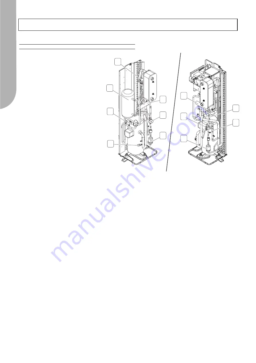
Hydraulic and chilling circuit components (Fig.2):
1. One-way valves (only IP units
), make the
refrigerant obligatorily pass through the appro-
priate heat exchangers, depending on the
operating cycle.
2. Low pressure switch
, with fixed setting. It is
installed on the suction pipe and blocks the
compressor if the operating pressures drop
below the tolerated values. It automatically
resets as the pressure increases. If it activates
frequently, the unit will block and can only be
restarted by resetting via the user interface
terminal.
3. High pressure switch
, with fixed setting. It is
installed on the delivery pipe and blocks the
compressor if the operating pressures exceed
the tolerated values. If it activates, the unit will
block and can only be restarted by resetting
via the user interface terminal.
4. Thermostatic valve
, of the type with external
equalizer.
Used as both a heat pump and chiller, it’s task
is to supply the evaporator correctly, keeping
the selected degree of superheat at a steady
level.
5. Dehydrator filter
of the mechanical type. Retains impurities and traces of moisture in the circuit.
6. Differential water pressure switch
. This is standard supply and is installed on the connections between the exchanger’s
water inlet and outlet. If it activates frequently, the unit will block and can only be restarted by resetting via the user interface
terminal.
7. 4-way cycle reversing valve
(
IP units only).
Reverses the direction in which the refrigerant flows when the summer/winter
operating modes change.
8. Fluid receiver
(
IP units only).
This is a plenum tank that accounts for the refrigerant charge variations required by the machi-
ne as the summer/winter operating modes change.
6
3
7
4
5
4
1
1
7
5
2
8
Fig.2


