24
ENGLISH
ENGLISH
Precautions to prevent ice from forming during winter periods at a standstill
If the system remains at a standstill during winter, the water could freeze and damage the unit’s exchanger and other compo-
nents.
There are three possible solutions to prevent this from happening:
- completely drain the system
, making sure that the exchanger is completely emptied.
If the unit is operating in conjunction with the Storage and Pumping Module, remember to also drain the tank using the fitting
with which it is supplied.
Remember to open the air vent to ensure that all the water completely drains out.
- use brine:
in this case
,
, the performances of the unit must be corrected, depending on the
% of brine
, and taking into account
the respective correction factors for the cooling capacity, power input, water flow rate and loss of pressure (
see following
table
). The real volume of the system must also be calculated, taking into account the correction factors of the system’s volu-
me as indicated in the “Maximum Volume of water” Section.
-
use the antifreeze heating element
built into the plate-type heat exchanger as part of the standard supply: use of this hea-
ting element prevents the heat exchanger from freezing and cracking.
If the unit operates in conjunction with the Storage and Pumping Module, ice can be prevented from forming inside the Storage
tank by installing the “
electric antifreeze heating element
”) handled by the controller of the unit with the same operating logic
as the antifreeze heating element in the plate-type heat exchanger.
Refer to the instructions supplied with this heating element when it is installed.
NOTE:
If this latter solution is used (use of the antifreeze heating elements) make sure that electricity is supplied continuously
throughout the entire period at which the unit remains at a standstill.
% of brine in weight
0%
10%
20%
30%
40%
Freezing temperature
0
-3.9
-8.9
-15.6
-23.4
Cooling capacity multiplier
1
0.99
0.98
0.97
0.95
Power input multiplier
1
1
0.99
0.99
0.98
Water flow rate multiplier
1
1.04
1.08
1.12
1.16
Water pressure drop multiplier
1
1.08
1.16
1.25
1.35
WET CONNECTIONS
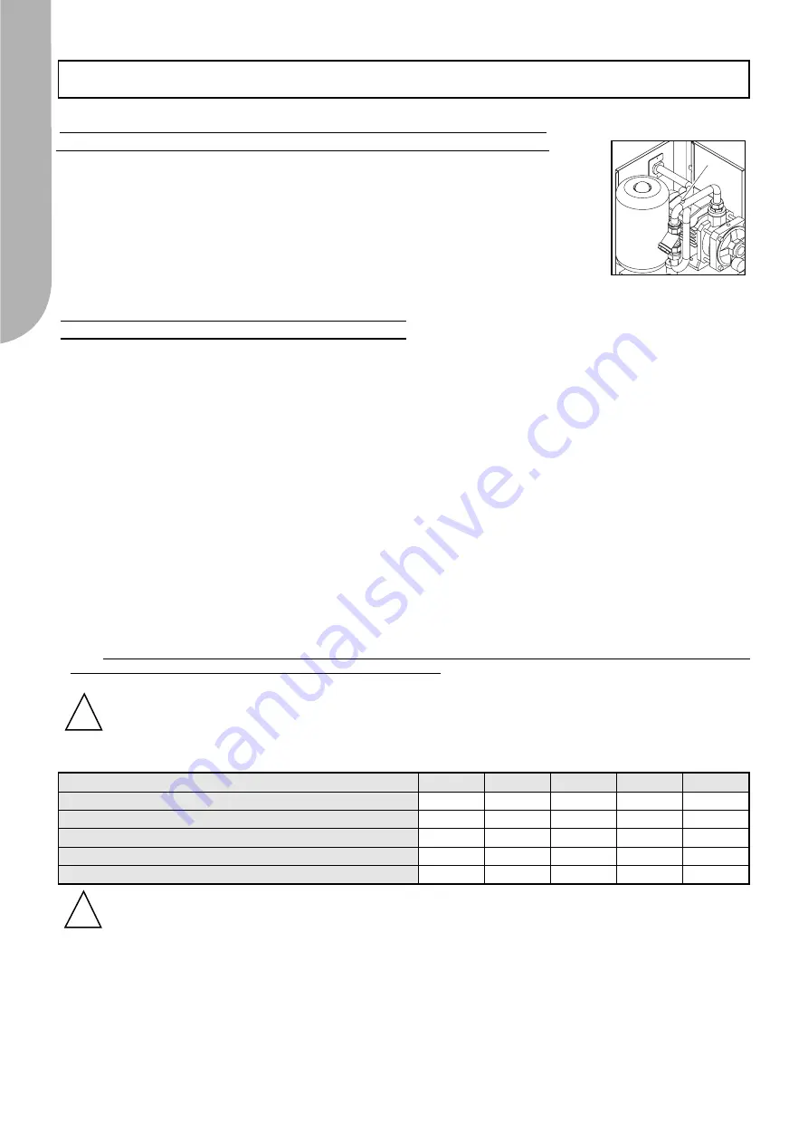
Charging the system and Air venting with the Storage and Pumping Module Mod. 30-55
Remember that the tank has a safety valve with a 300 kPa setting
.
To make the system easier and quicker to fill, open the air vent (1) under the cover of the unit using
a screwdriver.
Start the pump so as to eliminate all the air from the system.
Fig.1
NOTE:
Never use more than 40% of brine in Multiple stage pump versions of units operating in conjunction with the
Storage and Pumping Module.
!
Correction factor when brine is used:
NOTE:
the electric heating elements supplied do not protect the hydraulic pipes used to connect to the system.
!


