


34
Ferroli F 24 B
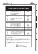
4.2 General view and main components
fig. 19
32
56
132
27
19
26
81
16
43
5
49
34
82
10
8
7
9
11
22
21
42
14
114
44
136
277
193 154
126
Key
5
Combustion chamber
7
Gas inlet
8
DHW outlet
9
Cold water inlet
10
CH flow
11
CH return
14
Safety valve
16
Fan
19
Combustion chamber
21
Gas injector
22
Ceramic burner
26
Combustion chamber insulation
27
Copper heat exchanger for c.h.
+ d.h.w.
32
Heating pump
34
Heating flow sensor
42
D.h.w. temperature sensor
43
Air pressure switch
44
Gas valve
49
Safety thermostat
56
Expansion vessel
81
Sparkelektrode
82
Ionisationelektrode
114
Water pressure switch
126
Flue gas safety thermostat
132
Flue gas deflector
136
Flow meter
154
Condense outlet
193
Siphon
277
Secondary heater exchanger