


10
Ferroli F 24 B
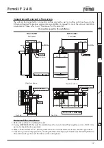
Minimum
A
B
D
5 cm
20 cm
60 cm
(via an openable panel)
C
20 cm
Table 1
fig. 2
2.2 Boiler location
The unit’s combustion circuit is sealed off from the installation room. The installation room must be
sufficiently well ventilated to prevent any dangerous conditions from forming in the event of even slight
gas leakage. This safety standard is required by the EEC Directive no. 90/396 for all gas units, including
those with a so-called sealed chamber.
Therefore the place of installation must be free of dust, flammable materials or objects or corrosive
gases. The room must be dry and not subject to freezing.
The boiler is design to be installed on a solid wall. The wall fixing must ensure a stable and effective
support for the appliance, using the bracket and fixings supplied.
If the unit is enclosed in cupboard or mounted alongside, there must be space for normal maintenance
work. Fig. 2 and tab. 1 give the minimum clearances to leave around the unit.
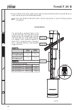
Drilling Template (Top Flue Application)
Select suitable mounting position for boiler, using the template mark flue outlet and boiler mounting
points. Drill two 10mm holes 70mm deep to accept the wall plugs. Fit standard wall plugs on the left and
right side and the special wall plug in the middle (fig. 3). Fix the wall bracket to the wall using standard
lock nut (M8) on both sides. Mount the boiler on the wall bracket and fix using the special antitheft nut
(M8) as described in the fig. 3. Using a core drill cut a 118mm diameter hole for the flue.
Fig. 3
A
A
B
D
C