
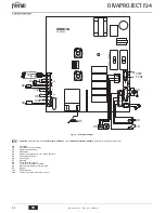

DIVAPROJECT F24
27
EN
cod. 3541F161 - Rev. 00 - 05/2014
4. SERVICE AND MAINTENANCE
All adjustment, conversion, commissioning and maintenance operations described be-
low must only be carried out by Qualified Personnel (meeting the professional technical
requirements prescribed by current regulations) such as those of the Local After-Sales
Technical Service.
FERROLI declines any liability for damage and/or injury caused by unqualified and un-
authorised persons tampering with the unit.
4.1 Adjustments
Gas conversion
The unit can work on natural gas or LPG and is factory-set for use with one of these two
gases, as clearly shown on the packing and data plate. Whenever a different gas to that
for which the unit is arranged has to be used, the special conversion kit will be required,
proceeding as follows:
1.
Disconnect the boiler power supply and close the gas cock.
2.
Replace the nozzles at the main burner, fitting the nozzles specified in the technical
data table in sec. 5.4, according to the type of gas used.
3.
Supplying power to the unit and open the gas cock.
4.
Change the parameter for the type of gas:
•
put the boiler in stand-by mode
•
press the RESET button for 10 seconds: leds flashing fast for two seconds
•
red LED ON
•
press the RESET button for 5 seconds: leds flashing fast for two seconds
•
turn the DHW knob (rif. 2 - fig. 1) to minimum (for Natural Gas operation) or onto
maximum (for LPG operation)
•
press the RESET button for 5 seconds: leds flashing fast for two seconds
•
Green LED ON
•
turn the heating knob (rif. 1 - fig. 1) to a minimum and then a maximum
•
the boiler will return to stand-by mode
•
place the knobs onto the set temperatures
5.
Adjust the minimum and maximum pressures at the burner (see relevant section),
setting the values given in the technical data table for the type of gas used
6.
Apply the sticker, contained in the conversion kit, near the data plate as proof of the
conversion.
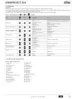
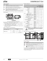
TEST mode activation
Press the
RESET button 3 times within 3 seconds
to activate
TEST mode
. The boiler
lights at the maximum heating power set as described in the following section.
If
TEST mode is activated
and enough hot water is drawn to activate DHW mode, the
boiler will stay in
TEST mode
but the 3-way valve switches to DHW.
Press the
RESET button 3 times within 3 seconds
to exit
TEST mode
. On exiting
TEST mode
, the set maximum heating power will not be modified.
The TEST mode is automatically disabled in any case after 15 minutes or on stopping of
hot water drawing (if enough hot water is drawn to activate DHW mode).
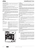
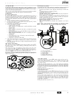
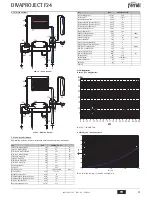
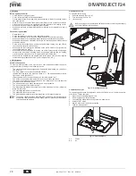
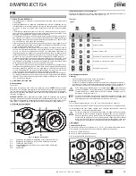
fig. 10 - TEST mode
Adjustment of pressure at the burner
Since this unit has flame modulation, there are two fixed pressure values: the minimum
and maximum, which must be those given in the technical data table according to the
type of gas.
•
Connect a suitable pressure gauge to pressure point
“B”
located downstream of the
gas valve
•
Remove the protection cap
“D”
undoing screw
“A”
.
•
Operate the boiler in
TEST mode
.
•
Turn the heating knob (ref. 1 - fig. 1) to max.
•
Adjust the max. pressure with screw
"G"
, clockwise to increase the pressure and
anticlockwise to decrease it
•
Disconnect one of the two Faston connectors from the modureg
"C"
on the gas valve.
•
Adjust the min. pressure with screw
"E"
, clockwise to decrease the pressure and
anticlockwise to increase it.
•
Reconnect the Faston connector detached from the modureg on the gas valve.
•
Check that the maximum pressure has not changed.
•
Refit protection cap
“D”
.
•
To end the
TEST mode
repeat the activation sequence or wait 15 minutes.
A
After checking or adjusting the pressure, make sure to seal the adjust-
ment screw with paint or a specific seal.
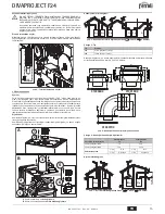
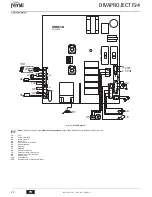
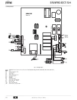
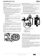
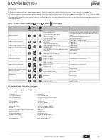
fig. 11 - Gas valve
A
- Protection cap screw
B
- Pressure point downstream
C
- Modureg cable
D
- Protection cap
E
- Min. pressure adjustment
G
- Max. pressure adjustment
Heating power adjustment
To adjust the heating power, switch the boiler to
TEST mode
(see sec. 4.1). Turn the
heating temperature control knob (ref. 1 - fig. 1) to minimum: the LEDs start flashing se-
quentially, yellow - green - red, indicating the heating power adjustment phase.
Turn the heating temperature control knob (ref. 1 - fig. 1) clockwise to increase the power
or anticlockwise to decrease it (see sec. 5.5). On reaching the desired power, press the
ECO button and the maximum power will remain that just set; the LEDs return to diag-
nose the TEST mode (see sec. 4.1) indicating memorisation of the maximum heating
power just set.
Exit
TEST mode
(see sec. 4.1).
Lighting power adjustment
To adjust the lighting power, switch the boiler to
TEST mode
(see sec. 4.1). Turn the
DHW temperature control knob (ref. 2 - fig. 1) to minimum: the LEDs start flashing se-
quentially, yellow - green - red, indicating the lighting power adjustment phase.
Turn the DHW temperature control knob (ref. 2 - fig. 1) clockwise to increase the power
or anticlockwise to decrease it (see sec. 5.5). On reaching the desired power, press the
ECO button and the lighting power will remain that just set; the LEDs return to diagnose
the
TEST mode
(see sec. 4.1) indicating memorisation of the lighting power just set.
Exit
TEST mode
(see sec. 4.1).
X3
C
D
B
A
D
C
E
G
Содержание DIVAPROJECT F24
Страница 85: ......
Страница 86: ......
Страница 87: ......
Страница 88: ...FERROLI S p A Via Ritonda 78 a 37047 San Bonifacio Verona ITALY www ferroli it ...


