

DIVAPROJECT F24
32
EN
cod. 3541F161 - Rev. 00 - 05/2014
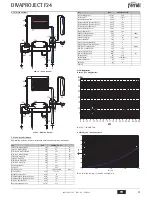
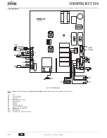
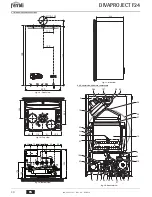
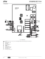
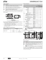
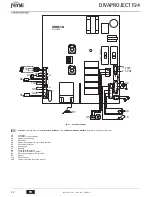
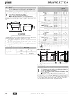
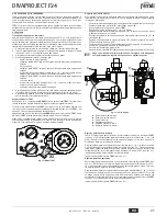
5.6 Wiring diagram
fig. 21 - Wiring diagram
A
Attention
: Remove the jumper on the terminal block
before connecting the room thermostat
or
the remote timer
control.
16
Fan
32
Heating circulating pump
34
Heating sensor
38
Flow switch
42
DHW temperature sensor
43
Air pressure switch
44
Gas valve
47
Modureg
49
Safety thermostat
72
Room thermostat (optional)
81
Ignition/detection electrode
95
Diverter valve
114
Water pressure switch
139
Remote timer control (optional)
X4
1
2
3
4
5
6
7
114
42
47
38
72
T.
L
N
230V
50 Hz
1
3
2
32
X7
1
44
16
81
1
2
3
4
5
6
7
8
9
10
11
X2
DBM33B
PT1
PT2
49
43
34
T.
1234
ON
DIP
PR08202
3.15A
250V
ac
2
3
4
95
1 2 3
139
Содержание DIVAPROJECT F24
Страница 85: ......
Страница 86: ......
Страница 87: ......
Страница 88: ...FERROLI S p A Via Ritonda 78 a 37047 San Bonifacio Verona ITALY www ferroli it ...


