
DIVA D F
52
EN
cod. 3542A640 - Rev. 00 - 11/2022
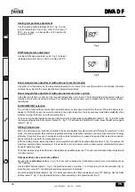
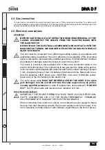
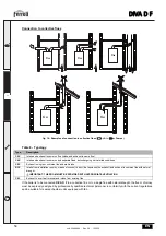
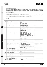
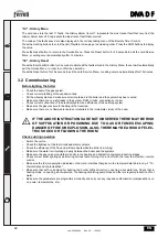
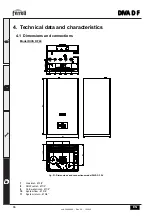
Connection with separate pipes
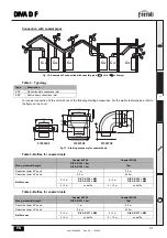
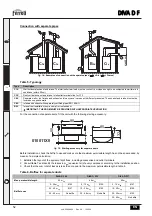
fig. 14 - Examples of connection with separate pipes (
= Air /
= Fumes)
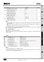
Table 5- Typology
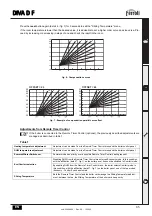
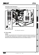
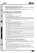
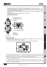
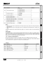
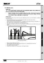
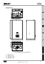
For the connection of separate ducts, fit the unit with the following starting accessory:
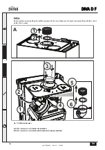
fig. 15 - Starting accessory for separate ducts
Before installation, check the baffle to use and make sure the maximum permissible length has not been exceeded, by
means of a simple calculation:
1. Establish the layout of the system of split flues, including accessories and outlet terminals.
2. Consult table 7 and identify the losses in m
eq
(equivalent m) of every component, according to the installation position.
3. Check that the sum total of losses is less than or equal to the maximum permissible length in table 6.
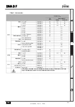
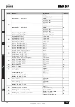
Table 6- Baffles for separate ducts
Type
Description
C1X
Wall horizontal exhaust and intake. The inlet/outlet terminals must be concentric or close enough to be subjected to similar wind
conditions (within 50cm)
C3X
Roof vertical exhaust and intake. Inlet/outlet terminals like for C12
C5X
Separate wall or roof intake and exhaust and in any case in areas with different pressures. The exhaust and intake must not be
located on opposite walls
C6X
Intake and exhaust with separately certified pipes (EN 1856/1)
B2X
Intake from installation room and wall or roof exhaust
IMPORTANT- THE ROOM MUST BE PROVIDED WITH APPROPRIATE VENTILATION
DIVA D F24
DIVA D F32
DIVA D F37
Max. permissible length
60 m
eq
48 m
eq
40 m
eq
Baffle to use
0 - 20 m
eq
Ø 43
0 - 15 m
eq
Ø 45
0 - 10 m
eq
Ø 47
20 - 45 m
eq
Ø 47
15 - 35 m
eq
Ø 50
10 - 20 m
eq
Ø 50
45 - 60 m
eq
No baffle
35 - 48 m
eq
No baffle
20 - 30 m
eq
Ø 52
30 - 40 m
eq
No baffle
C
5x
C
3x
B
2x
C
1x
max 50 cm
50
80
010011X0
80
32