background image

Kit5000_GB-A

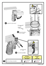
7

4

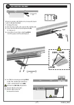
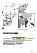
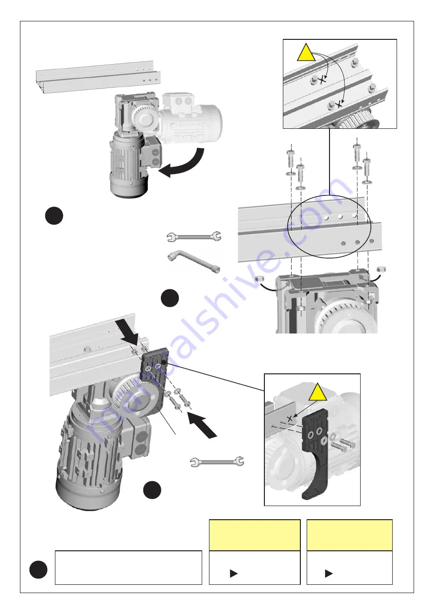
Rotate 90° to the motor.

5

Mount the motor

on it’s bracket.

!

6

Fix the belt guide 

(A)

.

A

- 27 -

!

Fermatic

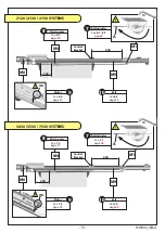
2120-2130-2150

2320-2420

Fermatic

3430

3530-7530

.

 Belt mounting and tighten

Follow step 6.5

page


13

Follow step 7.4

page


24

90°

10

10

10

Содержание KIT 5000

Страница 1: ...neral conditions of sales and mounting instructions are not binding and are only given for information purposes Only the french version can be used in case of legal action Power supply 220 240V AC 50...

Страница 2: ...otor mounting 9 Left side motor mounting 10 Passive edgemount security 11 Command box 12 Wiring 13 Horizontal safety device 14 Parameters 14 1 Initialization First power on 14 2 Control keyboard using...

Страница 3: ...gn manufacture and installation of an industrial door must respect the essential requirements of health and safety determined by the following European directives European Directives Manual door Motor...

Страница 4: ...RT This equipment must be protected from bad weather during transport The original packing is designed for all types of transportation means The packed kit withstands stacking of 4 others automatic ki...

Страница 5: ...device and an horizontal safety device according to the regulations that apply in the country of installation Function modes Options Horizontal safety device according to the regulations that apply in...

Страница 6: ...Adjuster screws 3430 3530 7530 M4 Door driving assembly M5 Driving assembly screws 3430 3530 7530 M6 Motor unit M7 Motor screws 2120 30 50 2320 2420 M8 Motor screws 3430 3530 7530 M9 Belt M10 Command...

Страница 7: ...40 2940 3240 A 2X 224 2X 224 2X 190 2X 200 2550 3150 3750 4350 4950 5550 6150 6750 B 377 347 370 365 355 Fermatic 3430 360 Fermatic 3530 7530 C 2X 601 2X 571 2X 560 2X 565 2905 3505 4105 4705 5305 590...

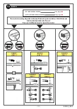
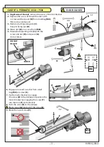
Страница 8: ...e motor right side of the rail Motor can be mounted in standard or 90 direction 90 MOTOR MOUNTING See page 26 Depending on the system installation the space available in the right end rail can be shor...

Страница 9: ...R 6 2 OK M1 1 Remove the 2 end covers 2 Insert the screws into the upper groove of the rail see drawings below 2120 2130 2150 1 2 2320 2420 2 1 13 13 6 C for cover M for motor T for belt adjuster C C...

Страница 10: ...the 2 screws Nota When mounting a Kit 5000 onto a manual Fermatic system already installed wedge the door unscrew the 2 door brackets A and push them aside to access the upper edge of the door 1 Fix d...

Страница 11: ...place it with spacer B from small bag M7 Fix spacer with a screw do not drive the screw 3 Position spacer A on the rail aligning with nut which is into the upper groove of the rail 2120 2130 2150 SYST...

Страница 12: ...hole e of motor bracket Block the 2 screws B C 170 2320 175 2420 13 6 Shoulder to the top Imperative 13 1 Right side of the rail remove the left screw of the end bracket and the left screw of the butt...

Страница 13: ...ews of the flange to block the belt 4 Remove the belt guide A 5 Engage the belt around the motor pulley then around the belt adjuster pulley 6 Tighten the belt Cut the belt at the middle of the drivin...

Страница 14: ...the screw C of the belt adjuster to tighten the belt the upper strand D must be horizontal 4 When the belt is tensioned block the screw B 5 Mount cover A Nota The belt adjuster may be moved laterally...

Страница 15: ...pace available in the right end rail can be short for mounting the motor in its standard configuration In that event it s possible to mount the motor left side of the rail LEFT SIDE MOTOR MOUNTING See...

Страница 16: ...530 1 Insert the 2 screws from small bag M3 into 2 slots of the rail 600mm 4th and 5th slot to central bracket see drawing below 2 Fix the belt adjuster M1 on the top of the rail Block the 2 screws 16...

Страница 17: ...imperative 6 Mount the door bracket 7 Mount the end cover Remove the blocks When mounting a Kit 5000 onto a manual Fermatic system already installed 1 Wedge the door 2 Remove the right end cover of th...

Страница 18: ...he rail There are 5 different ways to mount the motor CASE N 2 page 20 A CASE N 3 page 21 D C B CASE N 5 page 23 CASE N 1 page 19 CASE N 4 page 22 G F E OR 3430 3530 7530 3530 7530 90 MOTOR MOUNTING S...

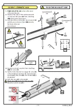
Страница 19: ...nd spacer 3 Left side of the end bracket mount spacer A with the second screw from M8 into the first hole of the rail Do not block 4 Engage a nut and a washer from small bag M8 on screw C 5 Tip the mo...

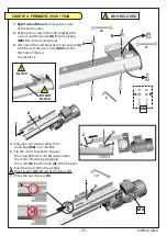
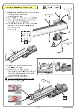
Страница 20: ...3 Left side of the end bracket mount spacer A with the second screw from M8 into the first hole of the rail Do not block 4 Engage a nut and a washer from small bag M8 on screw C 5 Tip the motor bracke...

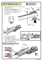
Страница 21: ...of the bracket 8 Push the screw E in the slot e Block spacer A and nut of the screw E 9 Block the nut of screw F DOOR CLOSED A B E F 24 17 32 6 17 1 Right side of the rail remove the screw of the end...

Страница 22: ...pacer B Block 4 Left side of the end bracket mount spacer A with the second screw from M8 into the first hole of the rail Do not block 5 Engage a nut and a washer from small bag M8 on screw E 6 Tip th...

Страница 23: ...e end bracket mount spacer A with the second screw from M8 into the first hole of the rail Do not block 4 Engage a nut and a washer from small bag M8 on screw D 5 Tip the motor bracket to engage the s...

Страница 24: ...rews of the flange to block the belt 8 5 5 6 7 8 Block A 4 10 4 Remove the belt guide A 5 Engage the belt around the motor pulley then around the belt adjuster pulley 6 Tighten the belt Cut the belt a...

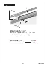
Страница 25: ...OX WIRING PARAMETERS Voir page 32 C B D A 17 10 1 Remove cover A with a screwdriver 2 Loosen screw B of about 1 4turn 3 Tighten the screw C of the belt adjuster to tighten the belt the upper strand D...

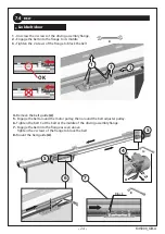
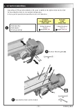
Страница 26: ...standard configuration In that event it s possible to mount the motor in 90 direction 26 Fermatic 2120 2130 2150 2320 2420 Fermatic 3430 3530 7530 Rail preparing Belt adjuster Driving assembly Follow...

Страница 27: ...90 to the motor 5 Mount the motor on it s bracket 6 Fix the belt guide A A 27 Fermatic 2120 2130 2150 2320 2420 Fermatic 3430 3530 7530 Belt mounting and tighten Follow step 6 5 page 13 Follow step 7...

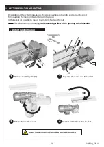
Страница 28: ...configuration In that event it s possible to mount the motor left side of the rail Nota The left side motor mounting is the same regardless of the opening side of the door Motor transformation Remove...

Страница 29: ...t adjuster M1 position and the driving assembly M4 position compared with standard mounting To mount the different parts of the Kit see the drawings next page Remember to reverse the drawings of the s...

Страница 30: ...racket Central Bracket M1 M1 M6 M6 M4 M4 M9 M9 See 6 1 6 2 page 9 Belt adjuster 7 See 7 1 page 16 Belt adjuster 7 See 6 3 page 10 Driving assy 8 See 7 2 page 17 Driving assy 8 See 6 4 page 11 Motor Se...

Отзывы: