background image

4

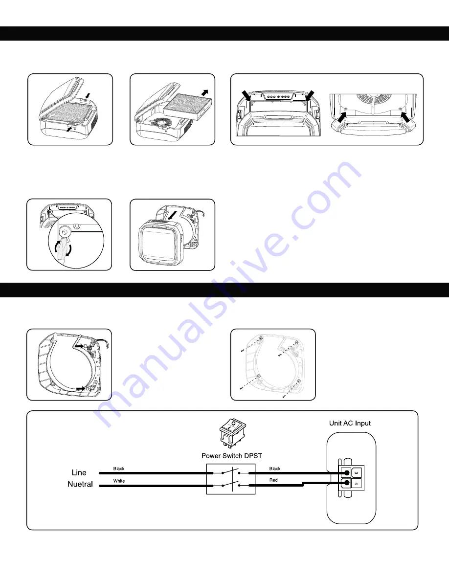
Place the air purifier face up on a 
flat, stable work surface. Open the 
access panel by pressing in latches 
on each side of the unit (Fig 3). 

Using provided template ensure electrical 
outlet box is located behind cable hole (A) 

JO 3FBS )PVTJOH BTTFNCMZ  'JH  %SJMM

holes and place anchors in wall.
If mounting on concrete, cinder block or 
brick type walls route the wires through 

UIFiQVODIPVUwIPMFNBSLFE #JO'JH

%JTDPOOFDU NBJO IPVTJOH BTTFNCMZ

from rear housing assembly. 
Separate main housing from rear 

IPVTJOH-JGUNBJOIPVTJOHBTTFNCMZ

away from rear mounting housing 
(Fig 8).

Open access panel and remove 
filter assembly by pulling out on 
top of side edges of frame, then 

MJGUJOH /05& SFNPWF BMM QMBTUJD

wrap from filters (Fig 4).

3FNPWFUIFGPVSIPVTJOHTDSFXT 'JHBOETFUBTJEFGPSSFBTTFNCMZ

At the location of the two upper 
housing screws (Fig 5), insert a flat 
head screwdriver and gently twist 
to release tab as shown in Fig 7. 
This will disconnect main housing 
assembly from the rear housing 
assembly.

MOUNTING REAR HOUSING AND MAIN ASSEMBLY

REAR HOUSING INSTALLATION & WIRING

Test the electrical outlet box first to ensure rated power requirements are met before beginning installation. 
Remove air purifier from its shipping carton and remove all packing material. 

Reference rear housing and locate desired mounting location. Again, it is strongly recommended at least 2 mounting anchors for the air purifier be mounted to 
an existing stud. 

A

B

Fig 3

Fig 7

Fig 4

Fig 8

Fig 5

Fig 6

Fig 9

Fig 10

Fig 11

Check for washers at all mounting 
screw locations (Fig 10). Pull wires 
from electrical outlet box through 
hole in rear housing. Align housing 
over anchors and securely install all 
mounting screws.

Attach wires from electrical outlet box to wires located inside rear housing using wire nuts. Match up line (black) and neutral (white) wires (Fig 11). Make sure all 
connections are made in accordance with federal, state and local codes and regulations.

Содержание Array AW1

Страница 1: ...fore installing Veuillez lire les instructions attentivement avant d installer le produit Lea cuidadosamente las instrucciones antes de instalar Array AW1 AeraMax Pro AM3 AM3 PC INSTALLATION GUIDE GUI...

Страница 2: ...H 1 Access panel 2 Filters 3 Filter frame 4 Main Assembly 5 Power Switch 6 Access panel latch 7 Access panel lock 8 Rear housing assembly 9 Control panel 10 Filter frame window KEY 1 6 2 7 3 8 9 10 4...

Страница 3: ...existing stud t SZXBMM ODIPST NN 0 t 1BO FBE 1IJMMJQT 4DSFXT 8 Fig 2 Americans with Disabilities Act ADA F TVSF UP GPMMPX BMM HVJEFMJOFT QFSUBJOJOH UP i0CKFDUT QSPUSVEJOH into a circulation path For m...

Страница 4: ...iver and gently twist to release tab as shown in Fig 7 This will disconnect main housing assembly from the rear housing assembly MOUNTING REAR HOUSING AND MAIN ASSEMBLY REAR HOUSING INSTALLATION WIRIN...

Страница 5: ...lled Carefully align the main assembly with the rear housing assembly Slowly press into place until snap is heard and there is no gap between the assemblies Fig 13 The unit should now support its own...

Страница 6: ...c s 2 Filtres 3 Cadre du filtre OTFNCMF QSJODJQBM 5 Commutateur PRVFU EV QBOOFBV EhBDD T 7 Verrou du panneau d acc s OTFNCMF EF CP UJFS BSSJ SF 9 Panneau de commande 10 Fen tre de cadre du filtre CL 1...

Страница 7: ...VTF MFDUSJRVF N DIFT OPO JODMVTFT t 5PVSOFWJT 1IJMMJQT O FU UPVSOFWJT DPVSUT U UF QMBUF non inclus t POOFDUFVST OPO JODMVT t JWFBV OPO JODMVT t PE MF EF NPOUBHF JODMVT t ODSBHFT EF QMBDPQM USF NN EF M...

Страница 8: ...s vis de montage 3FUJSFS MFT RVBUSF WJT EV CP UJFS JH FU FU MFT NFUUSF EF D U FO WVF EV r assemblage P TF USPVWFOU MFT EFVY WJT EV CP UJFS TVQ SJFVS JH JOT SFS VO UPVSOFWJT U UF QMBUF FU UPVSOFS douce...

Страница 9: ...vec l ensemble de CP UJFS BSSJ SF FUUF MF FO QMBDF lentement en appuyant dessus KVTRVh FOUFOESF VO E DMJD FU KVTRVh ce qu il n y ait plus d espace entre MFT FOTFNCMFT JH hVOJU devrait maintenant suppo...

Страница 10: ...Marco del filtro POKVOUP QSJODJQBM 5 Interruptor de energ a 6 Pestillo del panel de acceso 7 Bloqueo del panel de acceso POKVOUP EF MB DBSDBTB USBTFSB 9 Panel de control 10 Ventana del marco de filtr...

Страница 11: ...CSPDBT OP JODMVJEBT t 1IJMMJQT Z FTUPSOJMMBEPSFT DPSUPT EF DBCF B QMBOB OP JODMVJEPT t 5VFSDBT QBSB BMBNCSF OP JODMVJEBT t JWFMBEPS OP JODMVJEP t 1MBOUJMMB EF NPOUBKF JODMVJEP t ODMBKFT EF NBNQPTUFS...

Страница 12: ...T EF NPOUBKF Retire los cuatro tornillos de la carcasa Fig 5 y 6 y gu rdelos para volver a montar O FM MVHBS EF MPT EPT UPSOJMMPT EF la carcasa superior Fig 5 inserte un destornillador de cabeza plana...

Страница 13: ...nillos MJOFF DPO DVJEBEP FM DPOKVOUP QSJODJQBM DPO FM DPOKVOUP EF MB DBSDBTB USBTFSB FOUBNFOUF presione en su lugar hasta que se escuche un clic y no queden espacios FOUSF MPT DPOKVOUPT JH B VOJEBE BI...

Страница 14: ...Unit ___________ Web ID Sticker Here Floor ___ Area ___________ Unit ___________ Web ID Sticker Here Floor ___ Area ___________ Unit ___________ Web ID Sticker Here Floor ___ Area ___________ Unit __...

Страница 15: ...Avenue Itasca Illinois 60143 t 1 800 955 0959 t www fellowes com B r a n d s 2023 Fellowes Inc Part 412781 U S 1 800 955 0959 Canada 1 800 665 4339 Mexico 001 800 514 9057 CUSTOMER SERVICE SUPPORT www...

Отзывы: