background image

           
              Feiyu Electronics Company 


17 | 

P a g e


Vibration damping 

a)


The FY31AP flight controller algorithms can work under normal vibration levels. However if 

the  vibration  and  shock  experienced  by  the  sensors  are  excessive,  stabilization  can  fail  of 

the system can shut down altogether.   

b)


To achieve the best stabilization and flight performance, minimize the amount of vibration 

on the aircraft as best you can. 

c)


Examples of vibration reduction steps that can be taken: 

i)


Ensure your motors are mounted properly and squarely.   

ii)


Balance your propellers regardless of the manufacturer’s claim of perfect balance out 

of the box.   

iii)


Balance your motor bell housing (if possible). 

iv)


Ensure rigidity of your frame (no flexing with motor rotation). 

v)


Use appropriate propeller length and pitch for the size of your aircraft. 

d)


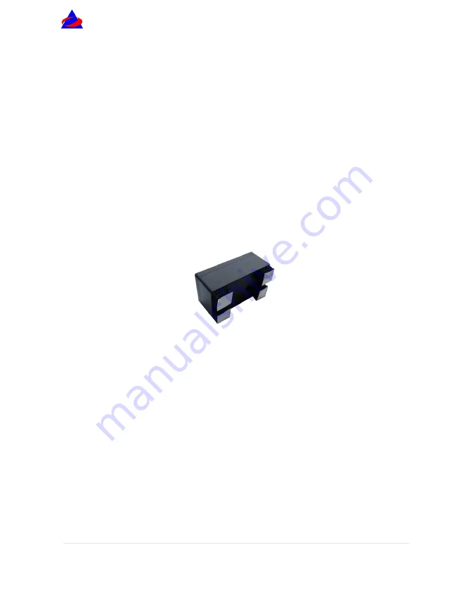
The FY31AP is supplied with the double-sided foam padding dampers. Please use them as 

shown below: 


Checking for Vibration Levels 

To confirm correct vibration damping, please follow this procedure:   

a)


After connecting all wires between to the FY31AP, including RC Receiver and ESC, install 

the unit on your plane (ensure correct orientation). 

b)


Run the plane engine or motor at different throttle levels. DO NOT TAKE OFF. 

c)


At  each  throttle  position,  observe  the  state  of  the  red  LED  light.  If  it  stays  OFF,  that 

means your vibration level is acceptable. 

d)


If instead the red LED lights up and stays


ON solid, then the vibration dampening is not 

enough.  You  will  need  reduce  the  level  of  vibration  on  your  aircraft.  Refer  above 

suggestions on vibration reduction. 


Содержание FY31AP

Страница 1: ...gy Co Ltd Rm B305 Innovation Building Information Industry Park Chaoyang Road Qixing District GuiLin CN www feiyu tech com Email feiyutech yahoo cn FEIYU TECH FY31AP Autopilot System Installation Operation Guide Rev 1 24 February 2012 ...

Страница 2: ...Electronics Company 1 P a g e Manual Update list Revision Date Updated page Topic updated 0 28 November 2011 N A First Release of Manual 1 24 February 2012 Page 21 Error in FY31AP connection diagram corrected ...

Страница 3: ... Mode Indicator Red or Blue light 11 GPS status vibration level indicator 12 FY31AP Interface 13 Dip Switch Function 19 GPS Receiver Connection 14 GPS Satellite Signal Lost During Autonomous Flight 15 UART Interface 15 FY31AP Electrical Connection and Diagram 16 Vibration damping 17 SW 1 and SW 2 Switch Settings for FY31AP 18 Connection layout of FY31AP 21 FY31AP installation Orientation Position ...

Страница 4: ...nowledge in flying remote controlled fixed wing aircraft If you are a complete beginner and have never flown one before we do not recommend you install this device on your own Please find assistance from an experience RC Pilot who may provide you with the basic knowledge required to use this device successfully If you are already an experienced flyer you will find the FY31AP installation to be eas...

Страница 5: ...ght giving you time to get your orientation and fly the plane back to safety v Autonomous flight with the GPS Receiver connected the FY31AP will enable you to fly fully autonomous with up to 8 waypoint settings using the FY Ground Control Station GCS software v Ground Control Station the FY GCS software will enable you to fly autonomously to up to 8 waypoints display in flight telemetry data and r...

Страница 6: ...ic pressure sensor At start up when five 5 or more GPS satellites are detected the FY31AP will note this as the Home position b The barometric air pressure and GPS data is merged to provide accurate relative altitude measurement c The GPS data enables the FY31AP to fly to 8 Waypoints via the FY GCS programme and Data Radio d Note that if the FY31AP is not connected to the GPS receiver autonomous f...

Страница 7: ...you to display the autopilot telemetry data onto your downlinked video display Refer the Hornet OSD Manual Ground Control Software You can download and use the software for free Refer the FY31AP GCS Manual to understand the GCS functions Data Radio You can fly via the GCS and 8 waypoint settable FY3ZT Remote Adapter allows you to fly the aircraft with only the FY31AP and Data Radio on board A simp...

Страница 8: ...60mA 3 3V Size 25 x 25x 15 mm Weight excluding wires 20g Temperature range 25 C 70 C Application The FY31AP can be installed in the following aircraft 1 Normal Traditional fixed wing planes 2 Delta winged plane with rudder 3 Delta winged plane without rudder 4 Plane without aileron 5 V tail plane with and without ailerons 6 Any other configuration please e mail us for enquiry service feiyu tech co...

Страница 9: ...line flight mode in this mode the waypoint will be set according to the flight path to automatic flight FY31AP Autonomous Flight Modes SW 2 a Three autopilot modes are incorporated into the FY31AP controlled by SW 2 b You may set the modes via a free receiver channel and a 3 position switch c Autopilot mode 1 Deactivated The autopilot function is not activated d Autopilot mode 2 Auto Return To Lau...

Страница 10: ...owever DO NOT forget to also set your throttle failsafe to between 25 to 50 to ensure the plane does not stall c Never set your throttle failsafe to zero If you do so your aircraft will RTL in a continuous stalled flight which will result in a crash d When flying under autonomous GCS control FY31P will control the throttle level based on the target speed refer GCS Manual However the throttle level...

Страница 11: ... Reset Procedure 1 Carry out this re setting procedure only if the above occur We do not recommend regular re setting It is not necessary and not recommended 2 The stabilizer unit does not need to be in a horizontal position during initialization However you must ensure there is no vibration during this process If you suspect shaking occurred just restart the initialization resetting process Initi...

Страница 12: ...tronics Company 11 P a g e Flight Mode Indicator Blue LED light By observing the flight indicator you can easily re confirm your Flight Mode switch settings of your radio Flight Mode Indicator Autopilot Indicator ...

Страница 13: ... can check the GPS lock status and vibration level by observing the Red LED Red LED light Status Too much vibration No GPS Need to initialize Gyro GPS location fixed 4 satellites Red LED Flashing Stay on solid Stay off solid Continuous flashing Continuous double flash each loop ...

Страница 14: ...ibration level indicator Interface pin panel Function DIP Aileron sensitivity knob 2 3 4 5 6 7 8 III IV II I 1 Jumper installed during gyro initialization Do not insert jumper during normal use ARROW FORWARD TOWARDS FLIGHT DIRECTION NOTE The pin I 1 2 3 4 is for the GPS module Pin I 3 outputs 3 3V of power DO NOT SUPPLY External Power to this pin you will burn the FY 31AP board ...

Страница 15: ...e GPS data protocol is a standard NEMA0183 and the statement must be GPRMC GPGGA NOTE The pin I 1 2 3 4 of the FY31AP pin interface is for the GPS module power supply i e The FY31AP pin I 3 outputs 3 3V of power via this pin DO NOT SUPPLY External Power to this pin or you will burn the FY 31AP board GPS Related Functions a If GPS cannot fix the aircraft location minimum 5 satellites only Mode 1 De...

Страница 16: ...odes In case GPS signal is lost during autopilot flight the FY31AP will keep its height and maintain its last flight direction After GPS signal is regained the plane will resume its Autopilot Mode UART Interface Position is II 1 II 2 II 3 II 4 The UART pin interfaces consist of GND power TX1 RX1 The characteristics are as follow Baud Rate 19200 Data bits 8 Stop Bits 1 Parity None Interface feature...

Страница 17: ...ower the Receiver and FY31AP b The FY31AP is connected to your RC Receiver via a 6 wire cable You need a minimum 6 Channel RC Receiver c Note that the wire is arranged according to color Wire color Receive channel White bundled with red black aileron Channel 1 orange elevator Channel 2 green throttle Channel 3 yellow rudder Channel 4 brown SW 1 Any free channel controlled by 3 way switch or dial k...

Страница 18: ...igidity of your frame no flexing with motor rotation v Use appropriate propeller length and pitch for the size of your aircraft d The FY31AP is supplied with the double sided foam padding dampers Please use them as shown below Checking for Vibration Levels To confirm correct vibration damping please follow this procedure a After connecting all wires between to the FY31AP including RC Receiver and ...

Страница 19: ...topilot Modes FY31AP Autopilot Modes is controlled via SW 2 IMPORTANT The Autopilot Mode SW 2 has controlling priority over the Flight Modes SW 1 If you wish to use the Flight Mode SW 1 you must de activate the Autopilot first SW 2 signal output 900 1200us 1200 1800us 1800 2100us Functional mode Return To Home RTH Autopilot Deactivated Auto Circling ACM Blue LED light indicator Continuous Double f...

Страница 20: ...out Rudder AIL OUT ELE OUT THR OUT RUD OUT Differential Servo 1 Differential Servo 2 Throttle Servo Rudder Servo 3 FY31AP connection for V tail aircraft with Aileron AIL OUT ELE OUT THR OUT RUD OUT Aileron Servo Differential Servo 1 Throttle Servo Differential Servo 2 4 FY31AP connection for V tail aircraft without ailerons AIL OUT ELE OUT THR OUT RUD OUT Differential Servo 1 Differential Servo 2 ...

Страница 21: ...r Servo Throttle servo Null 6 Camera Gimbal Stabilization AIL OUT ELE OUT THR OUT RUD OUT Roll Servo Tilt Servo Null Pan Servo Note The camera gimbal Roll Tilt and Pan servos will counter any linear movement of the camera mount You can move the camera at any angle and upon releasing the transmitter stick the FY31AP will maintain stabilization at that angle ...

Страница 22: ...keep it as horizontal as possible to the aircraft axis and as close as possible to the Centre of Gravity COG ARROW FORWARD TOWARDS FLIGHT DIRECTION Electric Motor GPS Module Data Radio OSD Module HORNET AIL OUT RUD OUT ELE OUT Blue Brown Yellow Green Red Black red white THR OUT ESC RC Receiver ...

Страница 23: ...hen in Stabilized Mode FY31AP installation Orientation Position and level has an arrow printed on the top of it Orientate the arrow towards the front of FY31AP horizontal and as close as possible to the Centre of ollowing diagram is its horizontal position Therefore ensure the FY31AP the horizontal position when the plane is in level flight FY31AP horizontal position and the plane s level flight i...

Страница 24: ...lization too high gain will cause oscillations of the aircraft You need to adjust the gain setting based on the ircraft The dials also control the direction of your servo movement Turning it clockwise or counter clockwise from 12 O clock will change the direction of stabilized flight against tilting roll and yaw Surface Movement Check as recommended in this manual then proceed to confirm correct c...

Страница 25: ...ng elevator action RUDDER Turn your plane clockwise or counter clockwise to see the rudder movement below Left aileron automatically moves upward Roll right Right aileron automatically move downwards Right aileron automatically move upwards Roll left Left aileron automatically move downwards Aileron Movement In Auto Stabilization Mode Rotate right Rotate left Rudder moves to the left Rudder moves ...

Страница 26: ...angle of the FY31AP to the horizontal level of the plane should not exceed 15 degrees 4 You can do this procedure with the aircraft on the ground or in the air 5 Setting the Neutral Value on the ground is quick and easy and will produce good stabilization results However recording neutral value on the fly will result in more accurate autonomous flight attitude control 6 NEUTRAL VALUE IMPORTANT NOT...

Страница 27: ...selage and wings perfectly level Step 4 ON your transmitter and zero all your trims Power up the FY31AP in Mode 1 Manual Mode Confirm there are no deflection to the Aileron Elevator and Rudder surfaces by adjusting your servo links Re confirm that your aircraft is perfectly level This is your aircraft Neutral position Step 5 While in Step 4 leveled position activate Mode 3 Auto Stabilization Mode ...

Страница 28: ...ne Step 6 Adjust your throttle to maintain leveled cruising flight Use your Aileron Rudder and Elevator trims to attain level flight while in full manual control By doing this you should be able to fly the aircraft in a straight line with the Aileron Elevator and Rudder sticks in the middle position i e fly using your trims only This condition of achieving level flight by trim adjustments alone an...

Страница 29: ...centre position and fly again You should see improvement in wing attitude Adjust until level of wing stabilization is acceptable 6 Elevator Rudder Gain Too much Elevator gain will show the tail moving up and down nodding Too much Rudder gain will show tail wagging Reduce gain until this flight over corrections disappears 7 Alternately if you find the flight correction is not enough too low stabili...

Страница 30: ...FY31AP GCS manual b Set the waypoints via the GCS software The maximum number of waypoints is 8 c After attaining good cruising speed via your throttle control switch SW 2 to Navigation Mode d Since the aircraft will maintain altitude monitor your cruising speed maintain throttle control to make sure the aircraft does not stall e The FY31AP should bring the aircraft through the Waypoints already p...

Страница 31: ...l the jumper as shown above Power ON the FY31AP and keep it stationary for at least 20 seconds You will notice the red light blink at two different rates or turns off Gyro re setting is complete Disconnect power unplug the jumper and keep it in a safe place for future use NOTE Carry out this re setting procedure only if the 3 conditions above occur The unit does not need to be horizontal during in...

Отзывы: