


OBID
®
i-
scan
Application-Note
ID ISC.ANT800/600
FEIG ELECTRONIC GmbH
Page 10 of 33
N11000-2e-ID-B.doc
2. Installation and wiring
2.1. Installation instructions
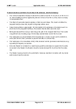
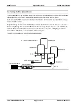
The antennas and power splitters on both sides of the gate are installed according to the diagram
below. The power splitters are connected only after calibrating the antennas. Since the Reader is
enclosed in a metal housing and the antennas couple into the Reader cables, the Reader should
be located at a distance of at least 50 cm (20 in) from the antennas. The second side mirrors side
one.
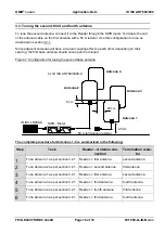
Figure 4 Installation diagram for one gate side including cabling
Two of the four base antennas are installed on one gate side, so that two base antennas always
face each other. All antennas should be installed vertically with the antenna opening/covers facing
down. The two antennas on a gate side must be oriented the same with their antenna open-
ing/covers facing the same way. In addition the antenna openings/covers should be located either
facing out (away from the gate) or in (towards the centre of the gate).
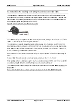
Please note the instructions in the installation guide for the ID ISC.ANT600/800-A/B.


