5 Connectors
Page 17 of 38
5 Connectors
Connectors
The connector I/O PINs are described from the cVEND PIN view. A cVEND PIN input must be connected to
one output or vice versa.
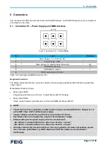
5.1 Connector X1
– Power Supply and MDB Interface
Pin
Label
Direction
1
Power Supply
– V
CC
(12 to 42 V DC)
-
2
Power Supply
– GND
-
3
Wake-Up (see X.X Standby Mode / Wake-Up)
I/O
4
MDB Master Receive
O
5
MDB Master Transmit
I
6
MDB Communication Common
-
Table 5: Pin Assignment MDB Connector (X1)
Required Connector:
The fitting complement for this connector consists of a 6-pole plug type Molex Mini Fit and the appending
crimp contact.
Manufacturer Ordering Code:
•
Molex 39-01-2060
Plug 6-pole, grid dimension 4.2 mm, 2-rowed, Molex Mini Fit housing
•
Molex 39-00-0065
Crimp contact, female, grid dimension 4.2 mm, AWG#22-28, Molex Mini Fit
NOTE:
•
The Device has to be supplied by a limited power supply according EN 62368-1 Chapter Q.1 or
with a NEC Class 2/LPS certified power supply.
•
Supply voltages outside the specifications may destroy the device.
•
Each Device has to be supplied by a separate external power supply.
•
External wiring for the power supply must be compliant with
- IEC 60332-2-1 and IEC 60332-2-2 for Wire Cross Section < 0,5 mm
2
- IEC 60332-1-2 and IEC 60332-1-3 for Wire Cross Section > 0,5 mm
2
•
All cables must be fed through a ferrite as close as possible to the device (impedance greater
than 700 ohms @ 800 MHz, e.g. Würth Elektronik 7427154). Cables can be bundled for
feedthrough.
Fig. 10: Connector X1
– Power/MDB
Содержание cVEND PIN
Страница 13: ...4 Mechanical Integration Page 11 of 38 Fig 6 cVEND PIN recommended front panel cut out ...
Страница 15: ...4 Mechanical Integration Page 13 of 38 Fig 8 cVEND PIN dimensions rear view ...
Страница 16: ...4 Mechanical Integration Page 14 of 38 Fig 9 cVEND PIN dimensions side view ...
Страница 18: ...4 Mechanical Integration Page 16 of 38 ...


