Page 5
Section IV Cont.
MODEL 183K
STANDARD & OPTIONAL FEATURES
1. The system consists of a Model UM183K controller,
a UM80K amplifier and a UCO30-4 cable, ( 4 foot
version), or a UCO30-15, ( 15 foot version).
2. The UM183K controller can control the siren and
warning lights.
3. A 60 amp progressive slide switch supplies 20 amps
of power per switch position.
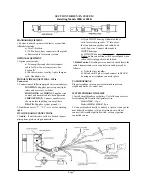
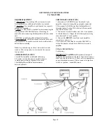
4. Horn Ring Transfer
a. Horn and Horn Ring connections on the rear
of a unit MUST be made to permit operation
of Manual siren and Yelp of Hetro Override.
See siren & warning light control for correct hook
up of the Horn Ring circuit.
5. Indicator lights to alert the user that there is an active
circuit at a glance.
Optional Equipment can include:
1. UPA2
a. UCAR-183K, P.A. cable
b. UMNCT-SB, P.A. microphone
2. UDMK, Dual Mode
SIREN & WARNING LIGHT CONTROL
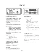
The progressive slide switch position 1, 2, & 3
turn on warning lights. Position 3 turns on the
siren and horn ring controls.
The toggle switch controls the siren’s mode of
operation during slide switch position 3.
OFF - No Siren.
MAN - Allows the siren to operate in manual mode.
AUTO - Siren & override functions automatically.
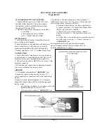
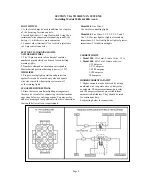
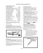
REAR CONNECTIONS
1. B1 terminals from left to right are:
a. Grd - Battery Ground
b. SPK - Siren Driver.
c. SPK - Siren Driver.
d. HORN - Spliced into the car horn circuit.
e. Ring - Spliced into the car horn circuit.
2. B2 terminals from left to right are:
a. +12V - Battery positive.
b. 1-2-3 - Slide switch output during position
1, 2, & 3.
c. 2-3 - Slide switch output only during switch
positions 2 & 3.
d. 3 - Slide switch output during position 3 only.
e. 1- Slide switch output during position 1 only.
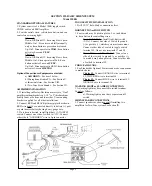
HORN RING CONNECTIONS
1. Cut wire apart between either the Horn Ring and the
Horn Relay or between the Horn Relay and the vehicle
Horn. Extend the wires to reach the rear of the control
unit.
2. Connect the wires to the B1 terminals screws marked
HORN and RING.
DO NOT REVERSE THE WIRES.


