SECTION III - BASIC SIREN SYSTEM
Model 180K
STANDARD & OPTIONAL FEATURES
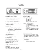
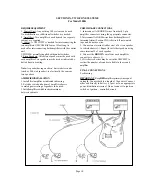
1. System consists of a Model 180K toggle switch,
CO29K cable and 80K Amplifier.
2. Switch controls siren, vehicle horn button, and can
control one warning light:
Choice 1:
Down-Off/Siren-Off : horn ring blows horn.
Middle-On 1: Siren rises and falls manually
only as horn button is pressed and released.
Up-On 2: Siren operates in
WAIL
; horn button
activates 5-second
YELP
.
Choice 2:
Down-Off/Siren-Off : horn ring blows horn.
Middle-On 1: Siren operates in Wail ; horn
button activates 5-second
YELP
.
Up-On 2: Siren operates in HI-LO; horn button
activates 5-second
HETRO
.
TOGGLE SWITCH INSTALLATION
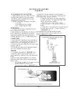
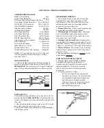
1. Drill 15/32” hole. Make connections first.
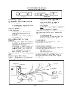
HORN BUTTON or FOOT SWITCH
1. Foot switch may be used in place of , or in addition
to, horn button for controlling siren.
Foot Switch Only
- Install light-duty switch
(1-3A). Connect one side of switch to ground
(-) or positive (+) ,whichever is most convenient.
Connect other side of switch to toggle switch
terminal #9. Do not use terminals #7 and #8.
Horn Button and Foot Switch
- Connect one
side of foot switch to ground (-) or positive (+)
to match horn button polarity. Connect other side
of switch to terminal #9.
Optional Connections or Equipment can include:
a)
AIR HORN
- See item 3 below.
b) Microphone & radio P.A. - See Section V.
c) Intrusion Alarm - See Section VIII.
d) Two-Tone Siren Sounds - See Section IX.
CHOICE of SOUNDS
1. See Standard & Optional Features and make connections
to match choice.
Choice #1:
Connect ORANGE wire to terminal
#3; WHT/RED wire to terminal #6.
Choice #2:
Connect BLUE wire to terminal #3;
ORANGE wire to terminal #6.
AMPLIFIER INSTALLATION
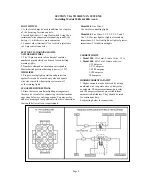
1. If installing in Harley-Davidson motorcycle, “float”
amplifier without brackets in 1-1/2” to 2” thick medium
density foam at bottom and four sides. Use mounting
brackets supplied for all other installations.
2. Connect RED and BLACK primary pigtails as shown.
RED wire must be connected directly to battery (+) post
or point nearest battery having heavy gauge wire.
3. If air horn is desired, install light duty (1-3A) SPST
switch. Connect one side of switch to +12V. Connect
other side to “AIR HORN” wire in 3-pin connector.
WARNING LIGHT or FLASHER CONNECTION
1. A warning light may be connected to switch terminal
#6 only as follows:
a) Warning light can not have separate on/off
switch.
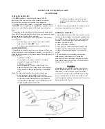
SIREN SPEAKER CONNECTIONS
1. Connect speakers as shown except if installing two
amplifiers for Two-Tone system. See Section IX.
Page 3


