Chapter 4: Wiring the INTEGRITY Lightbar in the Vehicle
22
Integrity Lightbar
7.
Separate all electronic equipment wiring from two-way radio equipment wiring.
8.
To avoid interference, keep two-way radio antennas a minimum of 18 in (45.7 cm) away from warning
equipment.
9.
Whenever possible, run full wire lengths. DO NOT splice the wires.
10.
Do not coil excess wire. Leave a drain loop for servicing.
11.
After drilling holes for wires, deburr them, smooth sharp edges, and insert grommets to protect the wires
from chafing.
12.
When you frame-ground the equipment, use the manufacturer-supplied ground locations in the vehicle.
IMPORTANT:
After the installation, frequently inspect the lightbar and mounting feet to ensure that all
fasteners and brackets are tight.
Connecting Power to the Lightbar
NOTE:
Plan the location of the wire-routing hole in the vehicle roof so that the power and communication
cables do not have tight bends and have some slack to allow disconnection on removal.
BATTERY EXPLOSION—To avoid a battery explosion, always disconnect the
negative battery cable first and reconnect it last. Avoid causing a spark when
connecting near or to the battery. The gases produced by a battery can cause a
battery explosion that could result in vehicle damage and serious injury.
SEAT REMOVAL PRECAUTION—If a vehicle seat is temporarily removed, verify
with the vehicle manufacturer if the seat needs to be recalibrated for proper airbag
deployment. Failure to follow this warning cause serious injury or death.
REVERSE POLARITY / MISWIRING—Reverse polarity or incorrect voltage may
damage the light. To avoid damage to the light, ensure that the battery voltage is
the same as the voltage rating of the light and that the correct polarity is observed.
If you are connecting to a cigarette lighter plug or 12 V outlet, connect the positive
wire to the center terminal and connect the negative wire to the outer terminal.
To make the power connections:
1.
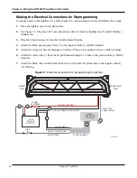
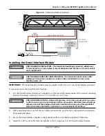
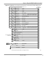
Ensure that the lines are adequately fused as shown in Figure 4.1 on page 23.
2.
From the lightbar, route the CAT5 control cable into the vehicle cab or trunk near the eventual location
of the Serial Interface Module. An input cable is also provided with the Interface Module.
3.
Route and connect the black lead from the lightbar to the vehicle battery’s ground (–GND) terminal.
4.
Route and connect the red lead from the lightbar through the supplied 40 A Maxi fuse holder at the
source, which is the positive battery terminal (+BAT).
Содержание Integrity44
Страница 2: ...blank page ...

