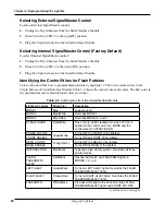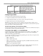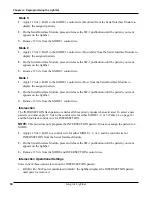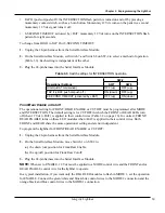
18
Chapter 3: Reprogramming the Lightbar
18
Integrity Lightbar
Mode 3
1.
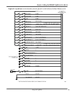
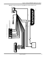
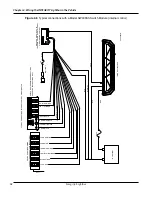
Apply 12 Vdc (+BAT) to the MODE 3 control wire (black/red) from the Serial Interface Module to
display the assigned pattern.
2.
On the Serial Interface Module, press and release the SW-1 pushbutton until the pattern you want
appears on the lightbar.
3.
Remove 12 Vdc from the MODE 3 control wire.
Mode 2
1.
Apply 12 Vdc (+BAT) to the MODE 2 control wire (blue/white) from the Serial Interface Module to
display the assigned pattern.
2.
On the Serial Interface Module, press and release the SW-1 pushbutton until the pattern you want
appears on the lightbar.
3.
Remove 12 Vdc from the MODE 2 control wire.
Mode 1
1.
Apply 12 Vdc (+BAT) to the MODE 1 control wire (blue) from the Serial Interface Module to
display the assigned pattern.
2.
On the Serial Interface Module, press and release the SW-1 pushbutton until the pattern you want
appears on the lightbar.
3.
Remove 12 Vdc from the MODE 1 control wire.
Intersection
The INTERSECTION flash pattern overrides all three priority modes when activated. To select a new
pattern, you must apply 12 Vdc to the control wire for either MODE 1, 2, or 3 (Table 3.2 on page 16)
and the blue/black control wire for INTERSECTION.
NOTE:
This procedure only programs the INTERSECTION pattern.
It does not assign the pattern to a
MODE.
1.
Apply 12 Vdc (+BAT) to a control wire for either MODE 1, 2, or 3, and the control wire for
INTERSECTION from the Serial Interface Module.
2.
On the Serial Interface Module, press and release the SW-1 pushbutton until the pattern you want
appears on the lightbar.
3.
Remove 12 Vdc from the MODE and INTERSECTION control wires.
Intersection Operational Settings
Select one of three options to turn on the INTERSECTION pattern:
• HIGH with +BAT power maintained (default): the lightbar displays the INTERSECTION pattern
until power is removed.
Содержание Integrity44
Страница 2: ...blank page ...

