


5
Installation Instructions
Note:
Steps 1 through 3 are also part of the installation
instructions for the submersible pump. This is done
to make sure all instructions are available if needed
during installation. As a result, steps 1-4 may
already be complete.
1. Connect the electrical conduit with approved
fittings to the submersible pump junction box.
2. Remove the submersible pump junction box cover,
and remove the compression seal by loosening
the screw (do not remove the screw). The seal
has four holes to accommodate a ground wire and
three-phase power from the
Eco
VFC.
Not installing a ground wire increases
the risk of potentially lethal electrical
shock and equipment failure. All holes
of the compression seal (contractors
plug) must be filled with wires or a
Celcon
®
rod to enable it to seal.
3. Verify that the power is OFF at the supply box.
Pull four wires from the spot where the
Eco
VFC
unit will be mounted into the submersible pump
junction box and feed through the compression
seal. Slide the compression seal into place and
tighten securely. Connect the three wires from
the connector assembly to the three phase
power wires coming from the
Eco
VFC. Connect
the fourth wire (ground) from inside to the pump
junction box ground lug.
EcoVFC accomodates
type TT or TN grounding configurations.
Note
: All wiring must conform to all applicable guidelines
in accordance with all federal, state, and local
codes. Failure to comply with all applicable
guidelines could result in an unsafe installation.
Use the following table for maximum wire length to
wire gauge for submersible wiring:
Wire Size
Maximum Run
5.26 mm
2
(10 AWG)
200 meters (650 feet)
3.31 mm
2
(12 AWG)
120 meters (400 feet)
2.08 mm
2
(14 AWG)
75 meters (250 feet)
4. Replace the cover of the pump junction box and
securely tighten in place.
The compression seal is not a
replacement for the vapor explosion
seals required by the NEC. All materials
used between the power supply box
and the submersible pump junction
box must be gasoline and oil resistant.
All wiring used within the EcoVFC must
be rated 90
°
C, 600V minimum. Failure
to comply with these, and all applicable
NEC guidelines, could result in an
unsafe installation.
5. Hang the
Eco
VFC on a vertical surface and
remove the front panel screw and front cover.
Install approved electrical conduits only at factory
knockouts on the
Eco
VFC enclosure.
Note:
Interference is created by several types of
equipment in a station (fluorescent lighting,
compressor, etc.), some more than others; this
interference can affect the operation of more
sensitive equipment (such as tank monitors and
electronic line leak detectors) which communicate
through data lines. When installing the
Eco
VFC,
FE Petro recommends that the power wires from
the Power Source as well as the power wires
to the IST or STP units with VS2 or VS4 suffix
(pump) be in their own steel conduit which is not
broken or routed through race ways. FE Petro also
recommends that all equipment be installed per the
manufacturer requirements for best results.
Note:
The
Eco
VFC must be mounted indoors in a non-
hazardous location with ambient temperatures
between 4° C (40° F) and 35° C (95° F).
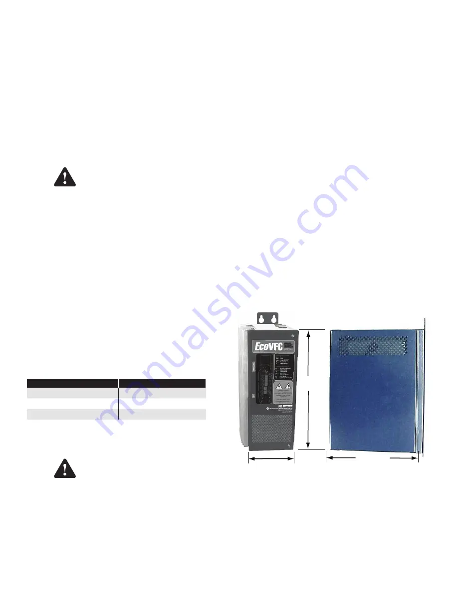
The EcoVFC measures 36.2cm (14.25”)H x 14.25cm
(5.50") W x 24.1cm (9.50") D (Figure 3).
Note:
To allow room for field adjustments and air
clearance, mount the controllers so they have 6” or
more of clearance on the top, bottom and right side
(cover side) , and 3" or more clearance on the left
side (heat sink side) . Install with the heat sink fins
vertical and the knock-outs down.
36.2 cm
14.0cm
24.1 cm
Figure 3: EcoVFC Dimensions
Warning
Warning
Содержание EcoVFC
Страница 26: ...2016FFS 228001102 Rev 10...


