background image

2nd edition, 31-03-2020

7000.05061, 2nd edition, 31-03-2020

7000.05061

Product description

11

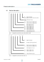
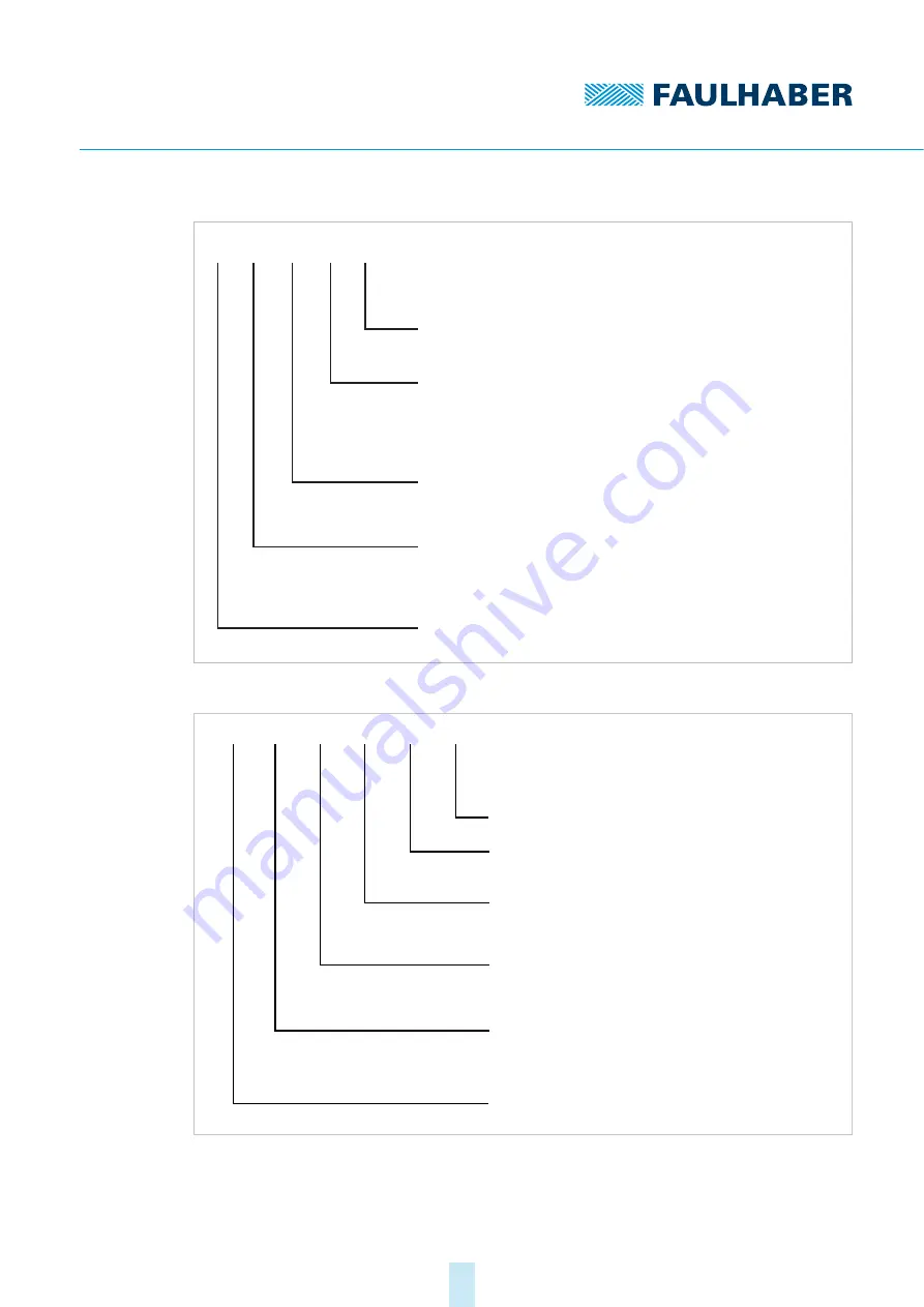
Fig. 3:

Designation key for motor series 1525, 1935 and 3153...BRC

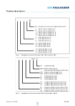
Fig. 4:

Designation key for motor series 2214, 3216 and 4221...BXT H

Brushless DC-motor with integrated electronics

Motor nominal voltage (6 V)
Motor nominal voltage (9 V)
Motor nominal voltage (12 V)
Motor nominal voltage (15 V)
Motor nominal voltage (24 V)

Shaft diameter 2 mm
Shaft diameter 3 mm
Shaft diameter 4 mm

Motor length 25 mm
Motor length 35 mm
Motor length 53 mm

...

...    BRC

...

...

BRC:

6:
9:
12:
15:
24:

U:
S:
K:

25:
35:
53:

Motor diameter 15 mm
Motor diameter 19 mm
Motor diameter 31 mm

15:

19:

31:

...

SC:

BX

:

T H

012:
024:

S:
W:

22:
32:

14:
16:
21:

...

...

...

BXT H

SC

G:

42:

Speed Controller

Motor family (14-pin)
External rotor technology with housing

Motor

(12 V)

nominal voltage

Motor

(24 V)

nominal voltage

Shaft diameter 3 mm
Shaft diameter 4 mm

Length of basic motor version 14 mm
Length of basic motor version 16 mm
Length of basic motor version 21 mm

Diameter of basic motor version 22 mm
Diameter of basic motor version 32 mm

Shaft diameter 5 mm

Diameter of basic motor version 42 mm

Содержание 22 BX4 SC Series

Страница 1: ...WE CREATE MOTION Technical Manual 22xx BX4 S SC 32xx BX4 SC 32xx BX4 SCDC 26xx B SC 1525 BRC 1935 BRC 3153 BRC 2214 BXT H SC 3216 BXT H SC 4221 BXT H SC EN...

Страница 2: ...ber GmbH Co KG cannot accept any liability for any errors in this document or for the consequences of such errors Equally no liability can be accepted for direct or consequential damages resulting fro...

Страница 3: ...2 Electrical connection of motor 18 4 2 2 1 EMC compliant installation 18 4 2 2 2 EMC suppressor circuit 18 4 2 2 3 Pin assignment 19 4 2 2 4 Connection examples 22 5 Description of functions 24 5 1...

Страница 4: ...ess mode only 35 5 4 8 Delayed Current Error only error output 35 5 5 Protective functions 36 5 5 1 I2 t current limitation 36 5 5 2 Overtemperature shutdown 37 5 6 Voltage output at motor 37 6 Commis...

Страница 5: ...sociated documents For certain actions during commissioning and operation of FAULHABER products additional information from the following manuals is useful 1 3 Using this document Read the document ca...

Страница 6: ...r avoidance Pre requirement for a requested action 1 First step for a requested action Result of a step 2 Second step of a requested action Result of an action Request for a single step action Abbrevi...

Страница 7: ...the manufacturer for information about individual use under special envi ronmental conditions 2 2 Safety instructions NOTICE Electrostatic discharges can damage the electronics Wear conductive work cl...

Страница 8: ...erved Machinery Directive 2006 42 EC Because of their small size no serious threats to life or physical condition can normally be expected from electric miniature drives Therefore the Machinery Direct...

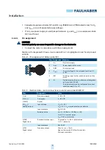
Страница 9: ...ed by means of digital option ally analogue Hall sensors or sensorless by means of the induced countervoltage EMF of the motors model series BRC The resulting lower speed limits are 1000 min 1 sensorl...

Страница 10: ...r family Motor nominal voltage 12 V Motor nominal voltage 24 V Shaft diameter 3 mm Shaft diameter 5 mm Motor length 32 mm Motor length 42 mm Motor length 50 mm Motor length 68 mm Motor diameter 22 mm...

Страница 11: ...diameter 4 mm Motor length 25 mm Motor length 35 mm Motor length 53 mm BRC BRC 6 9 12 15 24 U S K 25 35 53 Motor diameter 15 mm Motor diameter 19 mm Motor diameter 31 mm 15 19 31 SC BX T H 012 024 S W...

Страница 12: ...60 3242G012BX4 SCDC d Digital Hall 400 12 000 c 6 5 30 6 5 30 39 3242G024BX4 SCDC d Digital Hall 400 11 200 6 5 30 6 5 30 45 3268G024BX4 SC Digital Hall 400 6 500 6 5 30 6 5 30 99 Analogue Hall 50 6...

Страница 13: ...00 6 5 30 6 5 30 92 a The speed range depends on the maximum motor supply voltage b At metal flange c The drive must be reconfigured in order to reach the maximum speed d Option of analogue Hall senso...

Страница 14: ...ce in the immediate proximity of the motor Ensure that adequate heat dissipation is provided NOTICE Installation and connection of the motor when the power supply is applied can damage the device Prio...

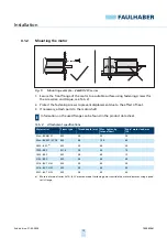
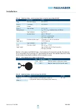
Страница 15: ...ach parts to the motor shaft Tab 2 Attachment specifications Information on the used flange can be found in the product data sheet Motor series Screw type Thread depth mm Max tightening torque Ncm Rad...

Страница 16: ...ions Connect the connections as per the pin assignment see chap 4 2 2 3 p 19 NOTICE Extreme static or dynamic loads on the ribbon cable can cause the cable to be damaged Make sure that the ribbon cabl...

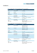
Страница 17: ...s tensile load 11 N Bending radius with one off installation 1 2 mm 1525 BRC 1935 BRC 1 00 AWG28 Tensile load 20 N Continuous tensile load 11 N Bending radius with one off installation 1 2 mm 3153 BRC...

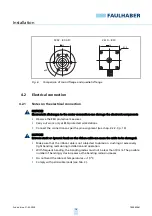
Страница 18: ...d directly at the unit with two windings through a suitable ferrite sleeve e g W rth Elektronik No 74270090 4 2 2 2 EMC suppressor circuit Suppressor circuit 1 Fig 7 EMC suppressor circuit with cerami...

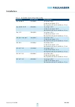
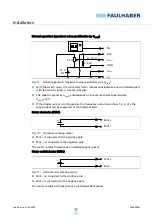
Страница 19: ...p Electronics supply 2 Umot Power supply of the motor 3 GND Common ground 4 Unsoll Control voltage for the set speed see chap 5 2 p 28 5 DIR Switching input for the rotation direction of the motor 6 F...

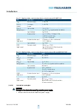
Страница 20: ...supply 6 5 30 V DC 3 GND Ground 4 Unsoll Analogue input Input voltage Uin 0 10 V Uin 10 V Up speed set value not defined Input resistance Rin 8 9 k Speed set value pro 1 V 1 000 min 1 Uin 0 15 V moto...

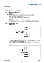
Страница 21: ...t Frequency output Max Up Imax 15 mA Open collector with 22 k pull up resistor 6 lines per revolution Wire Designation Value 1 Up Electronics supply 1525 BRC 4 18 V DC 1935 BRC 4 18 V DC 3153 BRC 5 30...

Страница 22: ...1 S Uin 0 15 V motor stops Uin 0 3 V motor runs 5 DIR Digital input Rotation direction input To ground or U 0 5 V anticlockwise U 3 V clockwise Input resistance Rin 10 k 6 FG Digital output Frequency...

Страница 23: ...here Unsoll 10 V If the digital output is configured as the frequency output see chap 5 3 p 31 the speed signal can be measured at the digital output Motor clockwise SCDC Fig 10 Clockwise rotating mot...

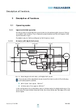
Страница 24: ...the digital Hall sensors The actual value for speed is determined using the time interval between the edges of the Hall sensor signals DIR Rotationaldirectioninput Evaluation rotational direction Unso...

Страница 25: ...tion via PWM signal at speed set value input Digital output Frequency output The number of lines per revolution which is output at the fre quency output can be set Possible values are 2 and 6 lines pe...

Страница 26: ...on Set value specification Analogue Digital output Frequency output Operating mode Speed controlled Speed filter Active Designation Explanation Set value specification The following set value specific...

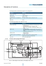
Страница 27: ...Phase PWM block commutator BL Motor PhaseA PhaseB PhaseC Iist RM Motor model kE Depending on the motor stable speed control is possible in this configuration from approx 1 000 min 1 Designation Explan...

Страница 28: ...ated at a certain speed In this case the set speed to be set is fixed using a parameter see chap 5 4 p 32 The following settings for the speed set value input Unsoll are possible Quick stop input low...

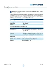
Страница 29: ...ion of 10 V corresponds to the value specified in the parameter nsetMax A linear conversion is performed between 0 V and 10 V Speed controlled operation nsoll nsetMax Unsoll 10 V Voltage controller U...

Страница 30: ...an be configured as switching levels Tab 13 TTL and PLC level values DIR Rotationaldirectioninput Evaluation rotational direction Unsoll nsoll Setpointinput Digitaloutput FG 22 k Electronicssupply Up...

Страница 31: ...ine the actual motor speed In this exam ple a signal contains 6 lines per motor revolution Fig 17 Signal structure of frequency output T Pulse duration Fig 18 Connection of an additional pull up resis...

Страница 32: ...alue for the briefly permitted maximum current Motor specific mA Motor continuous current Icont Value for the continuous current to which the motor is limited Motor specific mA Motor series Motor cont...

Страница 33: ...ter can be adapted using the FAULHABER Motion Manager The specified values apply in the case of 22 C ambient temperature and the nominal voltage for motor and electronics b Parameters can only be chan...

Страница 34: ...set value input Unsoll Motor specific min 1 Motor series Sensors Maximum speed value nsetMax a a Delivery state The speed range depends on the maximum motor supply voltage Unit 2232 BX4 S SC Digital H...

Страница 35: ...is used even if other parameters or speed set value specifications would result in a lower speed 5 4 8 Delayed Current Error only error output This parameter is only effective if the digital output ha...

Страница 36: ...Continuous current Icont The current is limited to the continuous current if the thermal model calculates a critical temperature Functionality of the I2 t current limitation The functionality of I2 t...

Страница 37: ...age output at motor The power stage of a motor with Speed Controller uses pulse width modulation PWM In the case of a fixed PWM frequency the duty cycle between the switch on time and switch off time...

Страница 38: ...actory The controller can optionally be optimised for specific applications In this case the digital controller operates at a sampling rate of 500 s Controller optimisation performed when commissionin...

Страница 39: ...7000 05061 2nd edition 31 03 20207000 05061 Commissioning 39 6 Reduce the controller gain until the system is stable again 7 Repeat steps 2 to 6 for the proportional integral component VI The motor i...

Страница 40: ...he motor is generally maintenance free Where the device is mounted in a cabinet depending on the deposition of dust the air filter should be regularly checked and cleaned if necessary 7 2 Troubleshoot...

Страница 41: ...act adapter 6501 00112 Programming adapter USB 6501 00096 Details on configuration can be found in the Motion Manager manual see chap 1 2 p 5 Details on the connection sequence can be found in the pro...

Страница 42: ...aulhaber GmbH Co KG are produced using the most modern production methods and are subject to strict quality inspections All sales and deliv eries are performed exclusively on the basis of our General...

Страница 43: ...dition 31 03 2020 Dr Fritz Faulhaber GmbH Co KG DR FRITZ FAULHABER GMBH CO KG Antriebssysteme Daimlerstra e 23 25 71101 Sch naich Germany Tel 49 0 7031 638 0 Fax 49 0 7031 638 100 info faulhaber de ww...

Отзывы: