2007-11-19
Page 20 of 35
IT321_Tech_doc_12
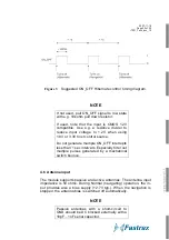
Figure 3
Suggested ON_OFF Hibernate control timing diagram.
NOTE
If not used, pull ON_OFF signal to low state
with e.g. 10kohm pull down resistor.
If used, note that the input is CMOS 1.2V
compatible. Use e.g. a resistive divider to
reduce input voltage to 1.2V when using
1.8V or 3.3V host control source.
Do not generate multiple ON_OFF interrupts
less than 1 sec intervals. Especially filter out
multiple pulses generated by a mechanical
switch bounce.
4.6 Antenna input
The module supports passive and active antennas. The antenna input
impedance is 50 ohms. During Normal (navigating) operation, the in-
put provides also a bias supply (+2.7V typ.). When the navigation is
stopped, the antenna bias is switched off automatically.
NOTE
Passive antennas with a short-circuit to
GND should be DC blocked externally with a
18pF…1nF serial capacitor.
Содержание IT321
Страница 15: ...2007 11 19 Page 15 of 35 IT321_Tech_doc_12 Figure 2 SiRFFlash utility settings...
Страница 25: ...2007 11 19 Page 25 of 35 IT321_Tech_doc_12 Figure 7 Tape and reel specification...
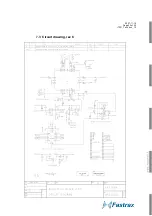
Страница 32: ...2007 11 19 Page 32 of 35 IT321_Tech_doc_12 7 3 Circuit drawing rev C...
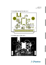
Страница 33: ...2007 11 19 Page 33 of 35 IT321_Tech_doc_12 7 4 Assembly drawing Top side rev C 7 5 Artwork layer 1 Top rev C...
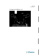
Страница 34: ...2007 11 19 Page 34 of 35 IT321_Tech_doc_12 7 6 Artwork layer 2 rev C 7 7 Artwork layer 3 rev C...
Страница 35: ...2007 11 19 Page 35 of 35 IT321_Tech_doc_12 7 8 Artwork layer 4 Bottom rev C...


