Fastrax EDC-141E Скачать руководство пользователя страница 14

4

2.6  Connection

•   Connecting to the RS-485/-4


NOTE:  Should you experience any control problems when using the Pelco-protocol, connect the ground plate (GND) to the control component.

  The dome camera can be controlled remotely by an external device or control system, such as a control keyboard, using RS-485 half-duplex, RS-4  
  duplex or simplex serial communications signals. Connect Marked Rx+, Rx- to Tx+ and Tx- of the RS-485 control system.
  If control system is RS-4, connect Rx+ (Tx+), Rx+ (Tx-) and Rx+, Rx- of the dome camera to Tx+, Tx- and Rx+, Rx- of the control device respectively.
•  Connecting Video out connector
  Connect the video out (BNC) connector to the monitor or video input.
•  Connecting Alarms
  AL to 8 (Alarm In)
  You can use external devices to signal the dome camera to react on events. Mechanical or electrical switches can be wired to the AL (Alarm In) and GND  
  (Ground) connectors. See Chapter 3 - Program and Operation for configuring alarm input.
  GND (Ground)

 NOTE:  All the connectors marked GND are common.

  Connect the ground side of the Alarm input and/or alarm output to the GND connector.
  NC(NO) TO 4 (Normal Close or Normal Open: Alarm Out)
  The dome camera can activate external devices such as buzzers or lights. Connect the device to the NC(NO) (Alarm Out) and COM (Common) connectors.  
  See Chapter 3 - Program and Operation for configuring alarm output.
•  Connecting the Power
  Connect the power of 4VAC 850mA to the dome camera.
  Use certified / Listed Class  power supply transformer only. 
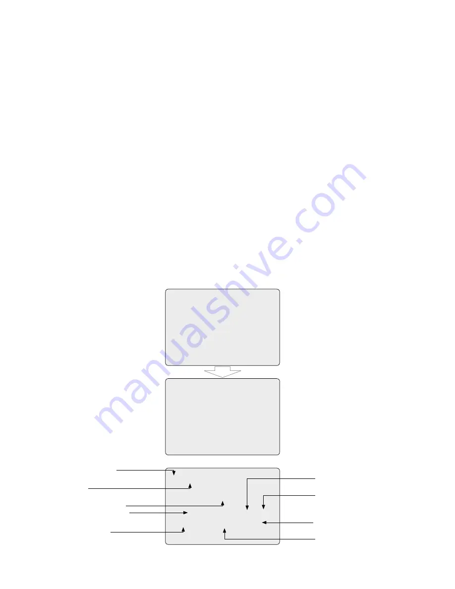
2.7  Getting Started

Once installed apply power to the dome camera. The dome camera will start a initializing sequence. When configuration is done, the following information is 
displayed on the keyboard controller’s LCD.

RAM TEST

CHECK NO. : OK!

CHECK AAAA : OK!
CHECK 5555 : OK!

FASTRAX II E Vx.xxx

CAMERA TYPE xxxx

WAIT DOME SETTING.

INIT TILT ORGIN SET OK
INIT PAN ORGIN SET OK

INIT CAMERA SET OK

00 PRESET

EMPTY DATA !

            T00                   DOMEID:000

ALARM:                  W_360.0,090.0

PRESET No.

TITLE

INFORMATION DISPLAY
COMMAND ON WORKING

ALARM DISPLAY

CAMERA TITLE

CAMERA ID

PAN & TILT DEGREE

VIEW DIRECTION

OSD Position

Содержание EDC-141E

Страница 1: ...Installation and Operating Manual Fastrax Dome Video Camera for Ceiling and Wall Mounting EDC 141E EDC 143E EDC 144E EDC 142E2...

Страница 2: ...15 3 1 Selecting Dome Camera 15 3 2 Accessing On Screen Menu Utility 15 3 3 How To Control On Screen Menu Utility 15 3 4 Auto Scan 16 3 5 Preset 17 3 6 Shortcut of Preset Program 18 3 7 Tour 18 3 8 P...

Страница 3: ...and wipe gently NOTE This is a class A digital device This digital device can cause harmful interference in a residential area in this case the user may be required to take appropriate corrective acti...

Страница 4: ...improving picture quality when you assemble bubble ring ass y up to 255 multiplexer Alarm Input up to 8 Sensor Siren Flashing light Alarm Output up to 4 J box Master keyboard up to 3 Slave keyboards...

Страница 5: ...h body and base of the camera Different version will not support alarm input and output The dome camera is for use in surface mounting applications and the mounting surface should be capable of suppor...

Страница 6: ...24VAC STP AWG 24 Sensor Alarm input up to 8 Siren Light Alarm output up to 4 BNC Alarm output 1 2 Alarm input 1 4 Power 24VAC Dome1 Dome1 Alarm output 3 4 Alarm input 5 8 Monitor BNC RS 485 Half Dupl...

Страница 7: ...Multiplexer Figure 5 Single Multiplexer Rear Keyboard controller Power 24VAC BNC Main Monitor BNC BNC RS 485 Pin No 4 RS 485 Pin No 6 J Box Back J Box Front AWG 24 Power 24VAC Power 24VAC Spot Monito...

Страница 8: ...ox Front AWG 24 Power 24VAC Power 24VAC Spot Monitor 1st Multiplexer BNC 2nd Multiplexer 2nd Main Monitor Spot output of the first multiplexer to be connected to 16th input of the second multiplexer A...

Страница 9: ...K B 1st Multiplexer BNC 2nd Multiplexer 2nd Main Monitor Spot Monitor for Slave K B Keyboard controller Slave Rear Spot output 1 of the first multiplexer to be connected to 16th input of the second mu...

Страница 10: ...iplexer nth spot out of the 2nd multiplexer to be connected to the nth spot monitor Each user will see the picture of the selected camera 1 31 n on nth spot monitor of the Mux 2 by selecting camera No...

Страница 11: ...the cable for communication terminated by setting the appropriate DIP switch Without proper termination there is potential for control signal errors Total length of the cable for communication should...

Страница 12: ...he service provider Example Port 1 Dome 1 Port 2 Dome 2 Port 16 Dome 16 If more than 16 dome cameras are installed using two or more multiplexers ID of the dome camera should be ID of MUX x No of came...

Страница 13: ...d On On Reserved S W On Off Function D1 S4 1 Enable Disable Alarm D2 S4 2 PAL NTSC NTSC PAL D3 S4 3 Endless D4 S4 4 RS 422 RS 485 RS 422 RS 485 D5 D6 D7 Protocol S5 1 S5 2 S5 3 Off Off Off Fastrax Pel...

Страница 14: ...m input GND Ground NOTE All the connectors marked GND are common Connect the ground side of the Alarm input and or alarm output to the GND connector NC NO 1 TO 4 Normal Close or Normal Open Alarm Out...

Страница 15: ...Accessing On Screen Menu Utility You can call up the On screen menu utility on your monitor by pressing MENU key on the keyboard controller the following On screen menu utility will appear 3 3 How to...

Страница 16: ...the Joystick downward to select END ANGLE Hold down the Ctrl PGM key while moving the Joystick to select the end position and zoom The end position angles should be larger than start position Release...

Страница 17: ...After selecting a blank position press and hold Ctrl PGM use the Joystick to control the direction of the camera and lens Ctrl Joystick 5 After aiming the camera view direction and lens control relea...

Страница 18: ...r2 has Preset3 Preset4 Preset5 Tour4 and Tour3 has Preset6 Pattern1 and Tour4 has Preset7 Tour1 executes as follows Preset1 Preset2 Preset3 Preset4 Preset5 Preset6 Pattern1 Preset1 Repeat Tour2 execut...

Страница 19: ...e Quick move Programmed speed 3 8 Pattern Fourth 4 Item of the Main menu Shortcut Ptrn The Pattern feature records user control of the selected dome camera for up to 240 seconds Up to four 4 patterns...

Страница 20: ...the Joystick up or down and push to right to enter the detail menu 2 Select the alarm input number by pushing the Joystick up or down and select the column you wish to setup Selected position will be...

Страница 21: ...o the right Press ESC to exit the program without saving 6 Pressing the Home key will delete programmed data Angles will be turned immediately 3 11 Privacy Zone Seventh Item of Main menu Hide up to 8...

Страница 22: ...tendable up to 2x of digital range 4x Zoom is extendable up to 4x of digital range MAX Zoom is extendable Max digital Zoom range EDC 142E2 OFF MAX NIGHT SHOT CONTROL FOCUS CONTROL FOCUS SETUP MODE AUT...

Страница 23: ...andle WB SETUP MODE AUTO R GAIN 210 B GAIN 155 EXIT ESC TO EXIT EDC 141E EDC 144E MODE MANUAL AUTO RGAIN 0 255 BGAIN 0 255 Use the AUTO mode for normal use RGAIN BGAIN modes are controllable only in M...

Страница 24: ...t filter is automatically turned on and off more dark condition than AE DARK AE DSS automatic exposure without switching IR Cut filter SLOW SHUTTER 1 60 1 30 1 15 1 8 1 4 1 2 1 50 1 25 1 12 1 6 1 3 1...

Страница 25: ...2 000 1 5 000 1 10 000 1 1 1 2 1 3 1 6 1 12 1 25 1 50 1 100 1 120 1 250 1 500 1 1 000 1 2 000 1 4 000 1 10 000 WDR MODE Wide Dynamic Range Technology uses two shutter speeds in alternative video fiel...

Страница 26: ...matically goes to Preset Tour Pattern Auto Scan after the keyboard controller has been idle for a amount of time For example if the Joystick controller is idle for 10 seconds the camera goes to preset...

Страница 27: ...y it is recommended that you set North as a Preset Recall the North Preset before enabling the directional title DOME OSD DISPLAY All display or title will disappear when DOME OSD DISPLAY sets OFF ARE...

Страница 28: ...r Angle is not sufficient enough to avoid ceiling obstructions please adjust Origin Offset of tilt angle as described below INITIALIZE DATA INITIALIZE DATA FACTORY DEFAULT ERASE PROGRAMMED DATA EXIT E...

Страница 29: ...ble for Keyboard is proprietary Cable for video is shielded Check termination of Video Dome cameras lose their positions Reset the cameras using the Dome configuration menus Check that the dome camera...

Страница 30: ...reset or pattern that is running and alarm names The display of each type of name setting can be enabled or disabled When the display of camera or area title name is enabled the information appears on...

Страница 31: ...4 ON Turn On Relay 1 4 OFF Turn Off Relay 10 ON Night Shot on 10 OFF Night Shot off 11 ON BLC on 11 OFF BLC off 12 ON Digital Zoom on According to digital zoom setting 12 OFF Digital Zoom off 13 ON D...

Страница 32: ...c or 3x up to 240sec in total Tours Up to 8 User programmable guard tours with vector scan Consisting of 42 presets and other functions with individual dwell time 3 to 99sec Selectable fast or slow ve...

Страница 33: ...e specific dome settings Adresses Up to 999 Dome ID s 3999 by software setting Up to 999 Dome ID s Up to 999 Dome ID s 3999 by software setting Keyboard control Direct mode control with Eneo EDC KBD M...

Страница 34: ...t Indoor Dome Housing with Clear Bubble 6 5 24VAC 74136 EDC OPS 2 24V Pendant Mount Outdoor Dome Housing with Sunshield Tinted Bubble 6 5 24VAC 74089 EDC CR1 Converter RS 232 RS 485 Repeater RS 485 74...

Страница 35: ...35 8 Dimensional Drawings Dimensions mm 99 0 45 R 3 R5...

Страница 36: ...Exclusive distribution through specialised trade channels only VIDEOR TECHNICAL E Hartig GmbH Carl Zeiss Stra e 8 63322 R dermark Germany Tel 49 0 6074 888 0 Fax 49 0 6074 888 100 www videortechnical...

Отзывы: